Turbomolecular Vacuum Pump
And now for something completely different: The Larch... (Monty Pythons)
Well, the following hasnt too much to do with gas turbines, though it might look somewhat familiar. I included this here because some people of course will be curious what such a thing looks like inside.
It is a turbomolecular high-vacuum pump that I had to strip down to check the bearings as it revealed problems spinning up. This pump requires a fore-vacuum of approx. 1mbar to operate. It spins at 72krpm and at that speed and the low pressure the gas cannot be considered as a continous medium but the molecules themselves contribute to the pumping effect. They can be considered to be kicked by the high-speed rotating vanes from the high-vacuum side to the forevacuum. This pump will generate a vacuum of about 10-12bar when operating properly, which would be fine for electron tubes or electron microscopy.
And here are the pictures:
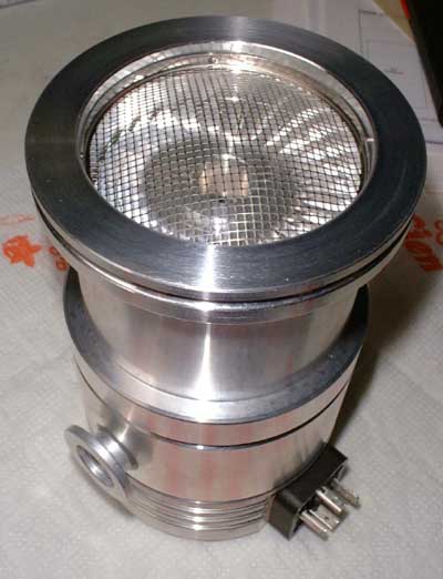 This is the complete pump, viewed
from the high-vacuum flange (suction side). The screen should probably protect the pump from foreign particles, but if an object of 1mm diameter (which will easily pass the screen) enters it, it
will be scrapped all the same. The first stage impeller can be seen below the screen. The overall diameter of the pump is 95mm, its height about 160mm.
This is the complete pump, viewed
from the high-vacuum flange (suction side). The screen should probably protect the pump from foreign particles, but if an object of 1mm diameter (which will easily pass the screen) enters it, it
will be scrapped all the same. The first stage impeller can be seen below the screen. The overall diameter of the pump is 95mm, its height about 160mm.
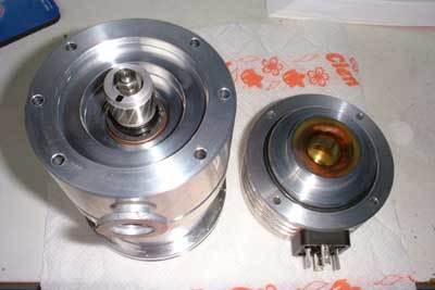 Here the rear end of the pump is
removed, showing the motor. This is a three-phase high-frequency motor that is driven by a highly sophisticated electronic drive- and protection circuit.
Here the rear end of the pump is
removed, showing the motor. This is a three-phase high-frequency motor that is driven by a highly sophisticated electronic drive- and protection circuit.
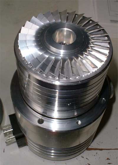 This picture shows the pump with the
top cover removed.
This picture shows the pump with the
top cover removed.
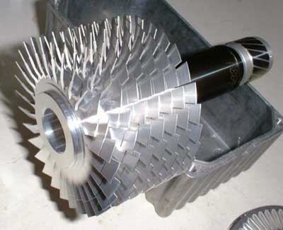 Here the seven-stage rotor is removed
along with the rotor of the drive motor and the bearing tunnel. The whole rotor is machined from a single piece of high-strength aluminium
Here the seven-stage rotor is removed
along with the rotor of the drive motor and the bearing tunnel. The whole rotor is machined from a single piece of high-strength aluminium
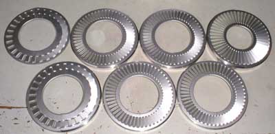 These are the stator vanes of the seven
pump stages, first top right, last top left. The stators are located in spacer rings, see picture above. The stators are diverted into two halves (not visible in this picture) to be able to arrange them
between the rotating vanes of the one-piece rotor.
These are the stator vanes of the seven
pump stages, first top right, last top left. The stators are located in spacer rings, see picture above. The stators are diverted into two halves (not visible in this picture) to be able to arrange them
between the rotating vanes of the one-piece rotor.
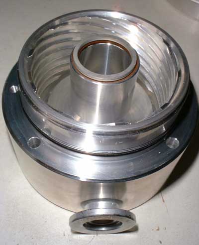 These spiraling grooves in the center
body of the pump (should) guide the gas to the fore vacuum flange. Yet I doubt that they are of too much effect, but on the other hand I guess the manufacturer wuoldnt have machined them if they were completely useless.
And low-pressure gas behaves significantly different from what we are familiar with, so who knows?
These spiraling grooves in the center
body of the pump (should) guide the gas to the fore vacuum flange. Yet I doubt that they are of too much effect, but on the other hand I guess the manufacturer wuoldnt have machined them if they were completely useless.
And low-pressure gas behaves significantly different from what we are familiar with, so who knows?
Now Ill have to figure out where to get the appropriate bearings (special vacuum hybrid ball bearings, probably incredibly expensive). Then Ill find out if disassenbly of this pump was a good idea.