The disassembly of the TS-21 commences. Consequently I keep on taking pictures of interesting design details that I will publish here.
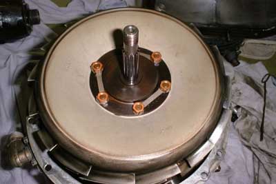 To get the gas generator further apart
the compressor wheel had to be removed. For my work on the Solent engine I had made a special crown-wrench that fortunately fit the compressor nut of this engine as well. I unlocked the crimped cupwasher and
after some application of brute force the nut was off...
To get the gas generator further apart
the compressor wheel had to be removed. For my work on the Solent engine I had made a special crown-wrench that fortunately fit the compressor nut of this engine as well. I unlocked the crimped cupwasher and
after some application of brute force the nut was off...
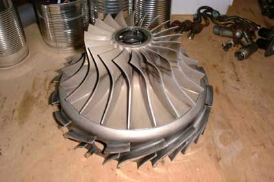
The compressor wheel could be removed easily. And of course I almost forgot to mark the position of the compressor wheel in relation to the shaft, but fortunately only almost.
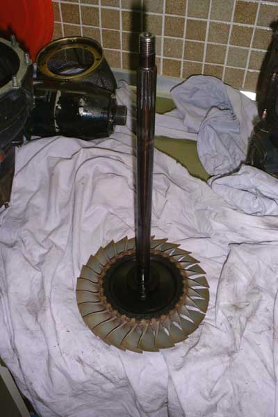 Thats what was left over after carrying
away the rest of the gas generator. The turbine disk is an integral part with the shaft. This eliminates the need to place a bore in the turbine disk, hence the strength of the disk is increased drastically.
Thats what was left over after carrying
away the rest of the gas generator. The turbine disk is an integral part with the shaft. This eliminates the need to place a bore in the turbine disk, hence the strength of the disk is increased drastically.
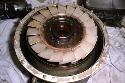 Thats the rear end of the gas
generator after removal of the turbine disk. Some orange fluid has settled on a few vanes. I wasnt able to figure out where this came from but it could easily be swept away with a soft cloth. I dont
want to apply any mechanical force to the surface of all the blades and vanes because they are possibly coated.
Thats the rear end of the gas
generator after removal of the turbine disk. Some orange fluid has settled on a few vanes. I wasnt able to figure out where this came from but it could easily be swept away with a soft cloth. I dont
want to apply any mechanical force to the surface of all the blades and vanes because they are possibly coated.
 The NGV is removed. This is an
amazing piece of engineering. As the vanes are shrouded by the turbine shroud so there wont build up any tension as they heat up during operation. Thus they wont start cracking like many single-piece cast
NGVs of small gas turbines.
The NGV is removed. This is an
amazing piece of engineering. As the vanes are shrouded by the turbine shroud so there wont build up any tension as they heat up during operation. Thus they wont start cracking like many single-piece cast
NGVs of small gas turbines.
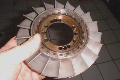
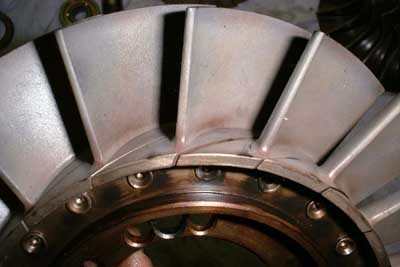 Here becomes clear that the NGV is
assembled out of separate vanes that are riven to a common hub ring. These vanes appear almost in mint condition, either they have been replaced recently or the engine runs so cool that they arent stressed at all.
Here becomes clear that the NGV is
assembled out of separate vanes that are riven to a common hub ring. These vanes appear almost in mint condition, either they have been replaced recently or the engine runs so cool that they arent stressed at all.
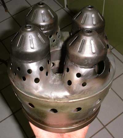 Oh man, thats a combustor! Four swirl
domes produce a combustible fuel-air mist together with the injector nozzles that are located on top of each of them. The primary zone (the area with the many smaller holes) tapers to a common annular dilution zone. The
large hole in the right front dome accepts one of the two spark plugs. This combustor is a true masterpiece of welding work!
Oh man, thats a combustor! Four swirl
domes produce a combustible fuel-air mist together with the injector nozzles that are located on top of each of them. The primary zone (the area with the many smaller holes) tapers to a common annular dilution zone. The
large hole in the right front dome accepts one of the two spark plugs. This combustor is a true masterpiece of welding work!
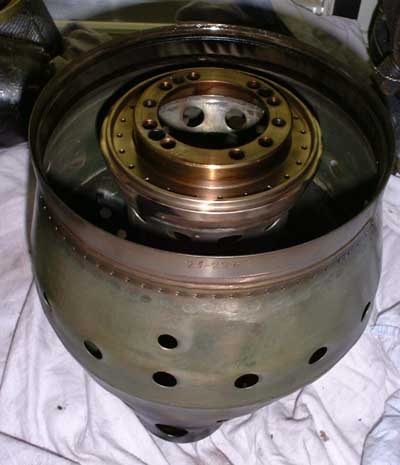 The combustor as viewed from the
NGV side. the centering ring slides over a flange on the shaft tunnel and as well meters cooling air to the inside of the NGV. The many small holes on the outside of the combustor are a passage for cooling air as well. The air
that enters the combustor through these holes is directed axially by a sheet that is welded into the combustor and cools the NGV tips and turbine shroud.
The combustor as viewed from the
NGV side. the centering ring slides over a flange on the shaft tunnel and as well meters cooling air to the inside of the NGV. The many small holes on the outside of the combustor are a passage for cooling air as well. The air
that enters the combustor through these holes is directed axially by a sheet that is welded into the combustor and cools the NGV tips and turbine shroud.
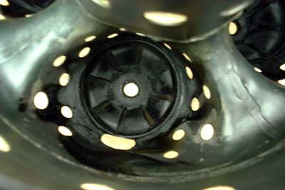 Thats one of the photos that were
harder to take because inside a combustor it is mainly dark. Using the flash wasnt a real alternative because the flash sensor would always see the light reflected by the upper region of the combustor, down in the depth it
was still dark as night. But somehow it did turn out and here you can see one of the swirl domes from the inside. Whats really curious is that most of the combustor is still shiny. Its a pity I dont
know how long this engine has been operated before.
Thats one of the photos that were
harder to take because inside a combustor it is mainly dark. Using the flash wasnt a real alternative because the flash sensor would always see the light reflected by the upper region of the combustor, down in the depth it
was still dark as night. But somehow it did turn out and here you can see one of the swirl domes from the inside. Whats really curious is that most of the combustor is still shiny. Its a pity I dont
know how long this engine has been operated before.
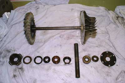 Heres all thats associated with the
rotor, shaft, suspension and the like. On top the complete rotor is shown. Beneath, from left to right are turbine labyrinth seal, spring washers, turbine bearing scavenge pump stator and rotor, turbine bearing (roller type),
turbine bearing oil shield, shaft reinforcement tube, compressor bearing (deep groove ball bearing), compressor bearing scavenge pump rotor and stator. Yes, you got it right. This small turbine actually has two
scavenge pumps located directly at the bearings!
Heres all thats associated with the
rotor, shaft, suspension and the like. On top the complete rotor is shown. Beneath, from left to right are turbine labyrinth seal, spring washers, turbine bearing scavenge pump stator and rotor, turbine bearing (roller type),
turbine bearing oil shield, shaft reinforcement tube, compressor bearing (deep groove ball bearing), compressor bearing scavenge pump rotor and stator. Yes, you got it right. This small turbine actually has two
scavenge pumps located directly at the bearings!
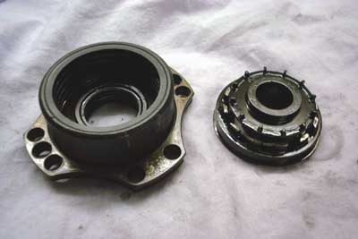 Thats the turbine labyrith seal and
scavenge pump. The pump rotor has tiny vanes that fling the oil outwards through small passages in the stator. The labyrinth seal has two sealing areas of different diameters, yet the cavity in between isnt pressurised with
compressor delivery air as its done in the Solent. Probably this isnt necessary because the oil pressure behind the scavenge pump is so low that virtually no leakage will occur.
Thats the turbine labyrith seal and
scavenge pump. The pump rotor has tiny vanes that fling the oil outwards through small passages in the stator. The labyrinth seal has two sealing areas of different diameters, yet the cavity in between isnt pressurised with
compressor delivery air as its done in the Solent. Probably this isnt necessary because the oil pressure behind the scavenge pump is so low that virtually no leakage will occur.
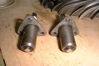
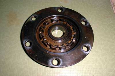 Thats the compressor scavenge pump
that is basically the same design as the one of the turbine bearing. One difference is that on the other side of this pump rotor there are many radial slots machined to form a hydrodynamic
oil seal together with the outer member of the pump. This will prevent leakage of oil to the cavity between compressor wheel and diffuser.
Thats the compressor scavenge pump
that is basically the same design as the one of the turbine bearing. One difference is that on the other side of this pump rotor there are many radial slots machined to form a hydrodynamic
oil seal together with the outer member of the pump. This will prevent leakage of oil to the cavity between compressor wheel and diffuser.
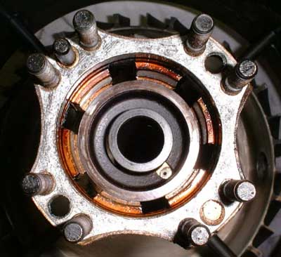
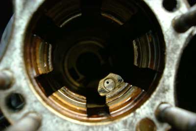 Thats a shot into the shaft tunnel
(turbine side). You can see a nozzle that will inject its oil jet directly into the rear bearing. Oil exiting the bearing is kept from re-entering it on the front by an oil shield (shown in the next picture).
Thats a shot into the shaft tunnel
(turbine side). You can see a nozzle that will inject its oil jet directly into the rear bearing. Oil exiting the bearing is kept from re-entering it on the front by an oil shield (shown in the next picture).
 This picture was taken upon
reassembly. The shaft reinforcement tube is in place as well as the oil shield cup. This cup has a cut-out at the place the oil jet nozzle is located to allow the passage of fresh oil into the bearing for
lubrication and cooling.
This picture was taken upon
reassembly. The shaft reinforcement tube is in place as well as the oil shield cup. This cup has a cut-out at the place the oil jet nozzle is located to allow the passage of fresh oil into the bearing for
lubrication and cooling.
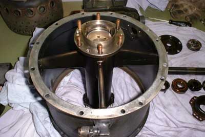 Thats the gas generator housing. It is
designed as a welded construction, made of stainless steel. It is displayed as seen from the compressor side. Two of the four support struts contain passages for the oil supply and return lines. This is a comparably heavy
component though neither of the parts of this engine can be claimed to be light-weight. This Russian construction is probably intended to be rock-solid rather than keeping weight as low as
possible. Almost all the nuts and bolts throughout this engine are copper-plated, probably to prevent corrosion.
Thats the gas generator housing. It is
designed as a welded construction, made of stainless steel. It is displayed as seen from the compressor side. Two of the four support struts contain passages for the oil supply and return lines. This is a comparably heavy
component though neither of the parts of this engine can be claimed to be light-weight. This Russian construction is probably intended to be rock-solid rather than keeping weight as low as
possible. Almost all the nuts and bolts throughout this engine are copper-plated, probably to prevent corrosion.
 These are the two surface spark plugs,
already cleaned. The spark gap seems to be shunted by a semiconductor because an ohm-meter reads about 50kOhms across the gap. I also checked the plugs with a geiger counter because sometimes a small
amount of radioactive material is used close to the gap to aid ionising it, but fortunately these plugs are clean.
These are the two surface spark plugs,
already cleaned. The spark gap seems to be shunted by a semiconductor because an ohm-meter reads about 50kOhms across the gap. I also checked the plugs with a geiger counter because sometimes a small
amount of radioactive material is used close to the gap to aid ionising it, but fortunately these plugs are clean.
 This was a hell of a cleaning job. It is
almost unbelievable how dirty your fingers can get though theres permanently water rinsing over them ;-). The dirt that is still left simply wont come off, so I usually call this surface conservation and leave it there. The
compressor housing is aready cleaned as well. The next few days i will clean the other components and then reassemble the gas generator. After that the free power turbine and gearbox are on schedule and after that the fuel
and oil pump with all the control functions. Still a lot to do.
This was a hell of a cleaning job. It is
almost unbelievable how dirty your fingers can get though theres permanently water rinsing over them ;-). The dirt that is still left simply wont come off, so I usually call this surface conservation and leave it there. The
compressor housing is aready cleaned as well. The next few days i will clean the other components and then reassemble the gas generator. After that the free power turbine and gearbox are on schedule and after that the fuel
and oil pump with all the control functions. Still a lot to do.
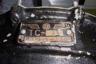 And thats the picture I probably should
have placed on top of it all. I asked a friend who learned Russian at school years ago about the exact spelling of this cyrillic designation, and he told me that the cyrillic C actually is pronounced S, so this engine is a
TS-21 as I already expected.
And thats the picture I probably should
have placed on top of it all. I asked a friend who learned Russian at school years ago about the exact spelling of this cyrillic designation, and he told me that the cyrillic C actually is pronounced S, so this engine is a
TS-21 as I already expected.
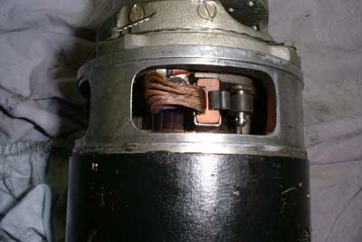 Work commences: This is a photo of
the starter motor with the protective cover removed. It is a four pole machine with carbon brushes of a size that Ive never seen before. Each brush has six flexible copper wires that connect it to the corresponding
terminal. The commutator has about the same size as the rotor. I guess this motor would make a nice power source for an application in Robot Wars...
Work commences: This is a photo of
the starter motor with the protective cover removed. It is a four pole machine with carbon brushes of a size that Ive never seen before. Each brush has six flexible copper wires that connect it to the corresponding
terminal. The commutator has about the same size as the rotor. I guess this motor would make a nice power source for an application in Robot Wars...
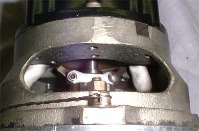 This flyweight-cutout mechanism is
located in the starter motor next to the commutator. As the starter spins up the gas generator rotor the centrifugal force increases until it eventually overcomes the spring force that holds
back the shaft located in the centre. As this moves forward a little it opens a switch that signals to the start control unit that the self sustain speed of the gas generator is reached and the starter motor can be de-energised
This flyweight-cutout mechanism is
located in the starter motor next to the commutator. As the starter spins up the gas generator rotor the centrifugal force increases until it eventually overcomes the spring force that holds
back the shaft located in the centre. As this moves forward a little it opens a switch that signals to the start control unit that the self sustain speed of the gas generator is reached and the starter motor can be de-energised
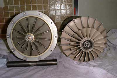 I simply had to place these three
pictures here. They show a direct comparison of the TS-21 and the Solent GTS gas generator components. Here it becomes actually clear how much larger the TS-21 components are so that a figure of 200hp peak seems reasonable
(compared to 70hp for the Solent).
I simply had to place these three
pictures here. They show a direct comparison of the TS-21 and the Solent GTS gas generator components. Here it becomes actually clear how much larger the TS-21 components are so that a figure of 200hp peak seems reasonable
(compared to 70hp for the Solent).
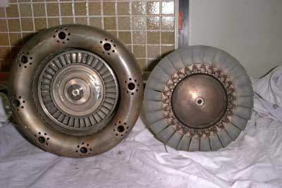 Here are the turbine wheels. The nozzle
area of the TS-21 must be about three times that of the Solent. Its quite funny that the outer diameter of both engines doesnt differ much. Thats manily the result of the single-stage axial diffuser
of the TS-21 and its straight flow combustor (as seen in the next picture).
Here are the turbine wheels. The nozzle
area of the TS-21 must be about three times that of the Solent. Its quite funny that the outer diameter of both engines doesnt differ much. Thats manily the result of the single-stage axial diffuser
of the TS-21 and its straight flow combustor (as seen in the next picture).
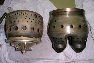 Both combustors. Though they are of
approximately the same diameter the combustor of the TS-21 is about 50% longer than the Solents. Yet if the combustors are compared from a fluid-dynamical point of view their length is approximately equal as the
Solent combustor has a turn in the gas flow (reverse flow design).
Both combustors. Though they are of
approximately the same diameter the combustor of the TS-21 is about 50% longer than the Solents. Yet if the combustors are compared from a fluid-dynamical point of view their length is approximately equal as the
Solent combustor has a turn in the gas flow (reverse flow design).
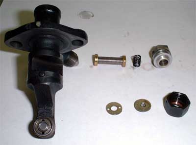 Today I disassembled one of the fuel
injectors to have a look at its construction. The components are the following: At the left theres the nozzle body. The top row from left to right are fuel filter element, filter seating spring
and the filter retaining screw with gasket. In the lower row there are swirl plate, nozzle orifice with swirl chamber, nozzle retaining nut. Th nozzle orifice is rather large, about 0.8mm so the
atomisation capabilities at lower fuel flow rates are rather poor. A friend of mine who owns a TS-21 as well and already got it running tested the nozzles for flow characteristics. At a pressure
of 2 bar the nozzle wont atomise the fuel sufficiently to sustain combuston while still flowing more than 10 liters of fuel per nozzle.
Maximum fuel flow for this engine is only about twice this figure, which will require a pressure of about 7 bar. For better low-power and starting characteristics it might be required to make new
nozzle plates, which wouldnt be this difficult from the manufacturing point of view, and to increase the operating fuel pressure significantly, say to 20bar. Yet this means a much more powerful injection pump would be required.
Today I disassembled one of the fuel
injectors to have a look at its construction. The components are the following: At the left theres the nozzle body. The top row from left to right are fuel filter element, filter seating spring
and the filter retaining screw with gasket. In the lower row there are swirl plate, nozzle orifice with swirl chamber, nozzle retaining nut. Th nozzle orifice is rather large, about 0.8mm so the
atomisation capabilities at lower fuel flow rates are rather poor. A friend of mine who owns a TS-21 as well and already got it running tested the nozzles for flow characteristics. At a pressure
of 2 bar the nozzle wont atomise the fuel sufficiently to sustain combuston while still flowing more than 10 liters of fuel per nozzle.
Maximum fuel flow for this engine is only about twice this figure, which will require a pressure of about 7 bar. For better low-power and starting characteristics it might be required to make new
nozzle plates, which wouldnt be this difficult from the manufacturing point of view, and to increase the operating fuel pressure significantly, say to 20bar. Yet this means a much more powerful injection pump would be required.
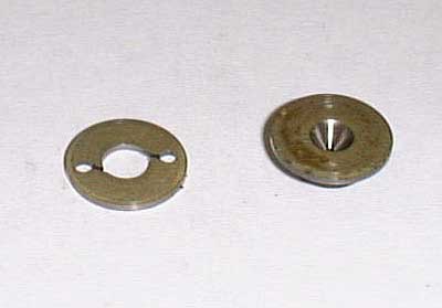 Thats a close-up of the swirl plate and
the nozzle. At the swirl plate the fuel enters through the two outer holes and then through the slots tangentially into the center bore. This bore opens into the swirl chamber of the nozzle and
while flowing further to the center, the swirl velocity increases. This intense rotation of the fuel causes it to break up into a fine spray as it exits through the nozzle bore. Unfortunately this design
doesnt include a return fuel bore in the back of the swirl chamber as to keep the swirl velocity high, yet returning most of the fuel back to the pump, thus having a low injection flow at still good atomisation.
Thats a close-up of the swirl plate and
the nozzle. At the swirl plate the fuel enters through the two outer holes and then through the slots tangentially into the center bore. This bore opens into the swirl chamber of the nozzle and
while flowing further to the center, the swirl velocity increases. This intense rotation of the fuel causes it to break up into a fine spray as it exits through the nozzle bore. Unfortunately this design
doesnt include a return fuel bore in the back of the swirl chamber as to keep the swirl velocity high, yet returning most of the fuel back to the pump, thus having a low injection flow at still good atomisation.