Today the ignition box of the TS-21 was due. Ive got two of them, but unfortunately one is damaged. It probably had been dropped on the face with the plugs, so now this face is badly warped and inside of the ignition box somethings rattling. As the supplied ignition boxes are somewhat on the heavy side Im considering to use a modified version of my bangbox instead. It would be much smaller and more lightweight. As well I might consider to change the engines electrical system to 12V. That is if I get proper replacements for the starter and FCU motors.
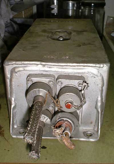 Thats a view onto the front face
of this ignition box. The supply voltage plug (lower right) is broken, the damage to the front isnt visible very well in this view. Yet the face is warped so badly that the supply plug interferes
with the lower of the two igniter output plugs so that some brute force was required to get them off.
Thats a view onto the front face
of this ignition box. The supply voltage plug (lower right) is broken, the damage to the front isnt visible very well in this view. Yet the face is warped so badly that the supply plug interferes
with the lower of the two igniter output plugs so that some brute force was required to get them off.
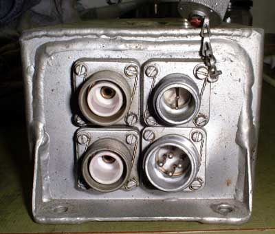 The plugs are removed. The
corresponding sockets are of very high quality, all the contacts are silver plated and the insulating parts made of ceramics. Unfortunately the Sockets wont come off because they are welded into the front face from the inside.
The whole cabinet is made of aluminium, at first I thought it was stainless but only the surface is protected by a coating that makes it look like this (...fortuantely).
The plugs are removed. The
corresponding sockets are of very high quality, all the contacts are silver plated and the insulating parts made of ceramics. Unfortunately the Sockets wont come off because they are welded into the front face from the inside.
The whole cabinet is made of aluminium, at first I thought it was stainless but only the surface is protected by a coating that makes it look like this (...fortuantely).
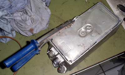 If the cabinet had been made of
stainless, I would have had real fun cutting it open. Unfortunately the cabinet is welded hermetically tight, in fact when I drilled the first hole to insert the cutter, there was a hissing noise from in- or outrushing air.
Theres also a screw in the centre of the top face that is welded tight and needed to be drilled out. So opening of the unit is a one-way task, but as its damaged anyway I dont mind
If the cabinet had been made of
stainless, I would have had real fun cutting it open. Unfortunately the cabinet is welded hermetically tight, in fact when I drilled the first hole to insert the cutter, there was a hissing noise from in- or outrushing air.
Theres also a screw in the centre of the top face that is welded tight and needed to be drilled out. So opening of the unit is a one-way task, but as its damaged anyway I dont mind
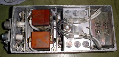 Finally the top cover is off. There
are no electric components that look familiar to someone in the electronic business except perhaps the wires, but even those are of uncommon kind. Theres some black dust almost everywhere in the box, I really
wonder where this came from due to the fact that the box was sealed.
Finally the top cover is off. There
are no electric components that look familiar to someone in the electronic business except perhaps the wires, but even those are of uncommon kind. Theres some black dust almost everywhere in the box, I really
wonder where this came from due to the fact that the box was sealed.
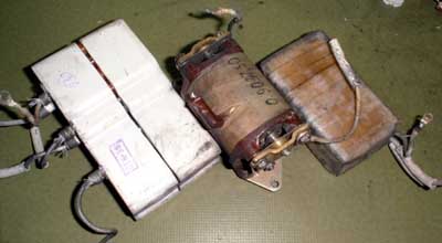 After some disassembly and
identification work, here are the main components of a single channel of this igniter. The box contains two complete, electrically separate channels like this - one for each spark plug. From left to right there are
silicone box containing the HT rectifier and the spark gaps, the self-exciting ignition transformer and the storage capacitor box.
After some disassembly and
identification work, here are the main components of a single channel of this igniter. The box contains two complete, electrically separate channels like this - one for each spark plug. From left to right there are
silicone box containing the HT rectifier and the spark gaps, the self-exciting ignition transformer and the storage capacitor box.
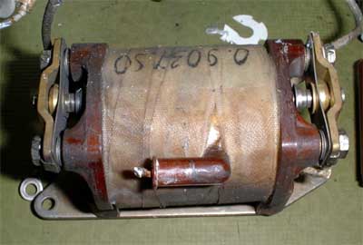 Thats the ignition coil with a
breaker contact at each side. The two contacts are electrically wired in series, probably to allow the igniter to still operate in case one set of contacts gets welded together during operation. In parallel to these
contacts there is the resonance capacitor, visible two pictures above as the brownish boxes. Concluding from the little wear of the contacts theres much too much dirt in the whole ignition box, really strange...
Thats the ignition coil with a
breaker contact at each side. The two contacts are electrically wired in series, probably to allow the igniter to still operate in case one set of contacts gets welded together during operation. In parallel to these
contacts there is the resonance capacitor, visible two pictures above as the brownish boxes. Concluding from the little wear of the contacts theres much too much dirt in the whole ignition box, really strange...
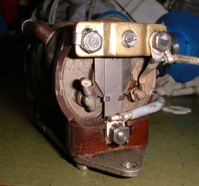 Heres one end face of the
ignition coil. The cut wire on the left terminal about at the centre of this picture was connected to the supply voltage while the right terminal is connected to the first breaker contact (metal plate on
top). The screw in the centre of this allows the adjustment of the gap of the breaker contacts. The sheet metal strip in the centre of the ignition coil carries the moving breaker contact and is connected to the second set of
contacts on the other side of the ignition coil by the wire to the right. I already operated this coil separately and considering the simple, almost antique design it works really well and produces
about 8kV at an input voltage of only 12V (estimated by the length of the spark). The high tension is present at a wire, located in the isolating elbow
tube at the top left in this picture. Its better visible in the lower centre of the picture above. Ill probably cement a pin in there to protect the rather thin wire from breaking. This coil would
make a perfect ignition source for any small homebuilt (turbocharger-) turbine. Its a pity that these units arent available easily.
Heres one end face of the
ignition coil. The cut wire on the left terminal about at the centre of this picture was connected to the supply voltage while the right terminal is connected to the first breaker contact (metal plate on
top). The screw in the centre of this allows the adjustment of the gap of the breaker contacts. The sheet metal strip in the centre of the ignition coil carries the moving breaker contact and is connected to the second set of
contacts on the other side of the ignition coil by the wire to the right. I already operated this coil separately and considering the simple, almost antique design it works really well and produces
about 8kV at an input voltage of only 12V (estimated by the length of the spark). The high tension is present at a wire, located in the isolating elbow
tube at the top left in this picture. Its better visible in the lower centre of the picture above. Ill probably cement a pin in there to protect the rather thin wire from breaking. This coil would
make a perfect ignition source for any small homebuilt (turbocharger-) turbine. Its a pity that these units arent available easily.
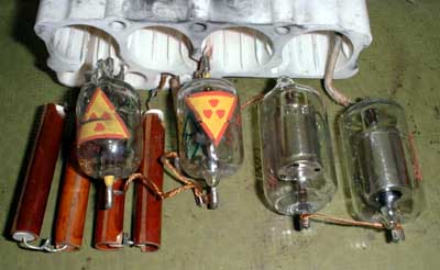 Thats the picture I like most.
Arent these colorful radioactivity signs cute? The tubes with these signs are the spark gaps that probably contain some radioactive material to aid ionisation of the gas contained in them. I checked them with a geiger
counter but outside of the glass tube theres amost no effect observable. The two tubes on the right are gas filled (cold-cathode) rectifier tubes. The brownish pipes on the left contain some resistors.
Thats the picture I like most.
Arent these colorful radioactivity signs cute? The tubes with these signs are the spark gaps that probably contain some radioactive material to aid ionisation of the gas contained in them. I checked them with a geiger
counter but outside of the glass tube theres amost no effect observable. The two tubes on the right are gas filled (cold-cathode) rectifier tubes. The brownish pipes on the left contain some resistors.
And thats the schematic for one of the channels of the ignition box. Click on the image for a (much...) larger version. Both channels are electrically identical. TR1 is the ignition coil with integral breaker contacts. C1 is the resonance capacitor and is connected parallel to both of the contacts. In principle this exciter works like a simple doorbell, though it oscillates at a much higher frequency due to the smaller inertia of the moving parts. In contrary to the secondary this primary circuit is completely independent of the ground. The high voltage generated in the secondary is rectified by the two tubes D1 and D2 and charges C2 directly and C3 through R1. C2 and C3 are an integral component. Once the voltage across C3 reaches the break-down voltage of the spark gap SG1, it becomes conductive and applies the voltage of C2 to SG2 which breaks down as well and supplies the charge stored in C2 through the primary of TR2 to the corresponding spark plug. TR2 is a current transformer, its primary consisting of just a single turn of the interconnection wire from SG2 to the connector X3 on a short bar of ferrite material. Its secondary is routed to a diagnostics plug but in this application it wasnt used. This ignition box is probably also used on other engines than the TS-21 APU where it might be important to observe the proper operation of the ignition system. If somehow no pulse current flows out of this ignition system, then there wont be a voltage spike induced in the secondary of TR2 and thus malfunction can be detected. R2 will ground any remainig charge on the terminals and makes handling of the deenergised unit safe.