Modified Solent Gas Generator as a Turbojet
After having reassembled the  Solent engine, throwing away the damaged components of
the original engine seemed a little bit hard to me. So I had a close look at each of them and decided that most of the components would still be usable or could be reworked. The most serious problems were the damaged NGV and
the turbine wheel.
Solent engine, throwing away the damaged components of
the original engine seemed a little bit hard to me. So I had a close look at each of them and decided that most of the components would still be usable or could be reworked. The most serious problems were the damaged NGV and
the turbine wheel.
On the other hand I still had the free power turbine wheel, which has the same hub diameter as the original wheel and only a slightly lower blade angle. It revealed a very thin layer of sputtered
metal from the destroyed gas generator turbine (less than 50µm), that might burn off, once the engine is running.
So I took the damaged NGV to a friend, whos father is a real wizard in all mechanical work
(he formerly constructed and built r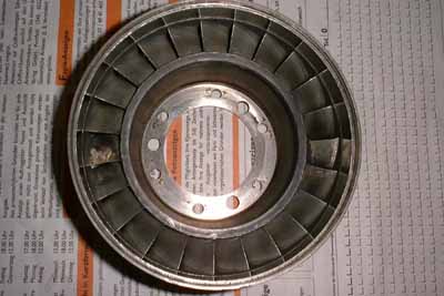 acing motorcycles, and their racing team won several competitions around the
world). He said he would try to MIG weld it with a special alloy welding wire. Some days later he gave it back to me, having accomplished a real artwork at it. I just had to grind the two welded vanes
back to shape (which was hell of a work due to the tough material, I ruined about five small tungsten grinders).
acing motorcycles, and their racing team won several competitions around the
world). He said he would try to MIG weld it with a special alloy welding wire. Some days later he gave it back to me, having accomplished a real artwork at it. I just had to grind the two welded vanes
back to shape (which was hell of a work due to the tough material, I ruined about five small tungsten grinders).
Finally I got the free power turbine wheel turned to size to fit into the turbine shroud which is
an integrated part of the NGV. Currently I figure out if I better attach a spline to the inside of the turbine bore to match the spline  on the turbine shaft. Calculations show that I will have to expect about 30Nm of torque at the turbine-shaft joint. Possibly that could be taken over by friction when the
turbine nut is tightened and secured, but I dont even want to imagine what happens if the turbine wheel comes loose. The splined joint would require welding a layer of material into the turbine wheel
bore, turning to size and then pinching out the teeth. And after that a heat treatment of the wheel would be required to remove any stress from the
wheel hub and to restore the capabilities of the material. Quite a lot of work. But maybe there is still another option.
on the turbine shaft. Calculations show that I will have to expect about 30Nm of torque at the turbine-shaft joint. Possibly that could be taken over by friction when the
turbine nut is tightened and secured, but I dont even want to imagine what happens if the turbine wheel comes loose. The splined joint would require welding a layer of material into the turbine wheel
bore, turning to size and then pinching out the teeth. And after that a heat treatment of the wheel would be required to remove any stress from the
wheel hub and to restore the capabilities of the material. Quite a lot of work. But maybe there is still another option.
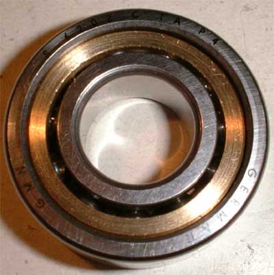
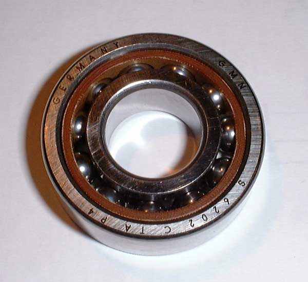 Both turbine shaft bearings
will have to be replaced. The original bearings are of the standard 7202 single row angular contact bearing size, but they are of a very high-quality make. There are appropriate bearings commercially available, but
they are well above my financial capabilities (at least with regard to this project). So I purchased some standard 7202C (GMN number S 6202C TA P4) spindle bearings and will exchange the resin cage with something
more temperature-resistent (probably brass, aluminium alloy like the original, or titan if it wont be too hard to machine). One advantage of
the angular contact bearings is that they can be taken apart easily and without damage to the components.
Both turbine shaft bearings
will have to be replaced. The original bearings are of the standard 7202 single row angular contact bearing size, but they are of a very high-quality make. There are appropriate bearings commercially available, but
they are well above my financial capabilities (at least with regard to this project). So I purchased some standard 7202C (GMN number S 6202C TA P4) spindle bearings and will exchange the resin cage with something
more temperature-resistent (probably brass, aluminium alloy like the original, or titan if it wont be too hard to machine). One advantage of
the angular contact bearings is that they can be taken apart easily and without damage to the components.
The turbine wheel centering adapter will have to be designed completely new to match the different size and shape of the power turbine centering stud. This component also might take over the torque of the turbine wheel.
The turbine bearing retaining part will probably have to be reworked completely, probably with slightly different inner dimensions to fit the new turbine wheel centering adapter.
Then some balancing will have to be done to the rotating assembly. To complete the turbojet the inlet cover will have to be spun to size, the power turbine NGV, which also serves as a part of the comustion chamber inner shroud, will have to be modified and an inner and outer exhaust nozzle cone, made of rolled stainless steel sheet, will have to be added. So stay tuned for completion of this engine (will take time, though).
Added 11/28/2000
 Today I finished the new turbine
centering adapter (hub). This Picture shows it, already shrunk onto the turbine wheel stud. I finally decided not to manufacture a new spline to connect the shaft, but to shrink all the components together.
Due to this the hub is made of high tensile strength steel, which features less thermal expansion than the nimonic the turbine wheel is made of. So the fit will strengthen when the engine heats up. The small holes on the
step between the two labyrinth seals provide cooling air to the back of the turbine wheel. Hell of a work was this piece due to the tough material.
Today I finished the new turbine
centering adapter (hub). This Picture shows it, already shrunk onto the turbine wheel stud. I finally decided not to manufacture a new spline to connect the shaft, but to shrink all the components together.
Due to this the hub is made of high tensile strength steel, which features less thermal expansion than the nimonic the turbine wheel is made of. So the fit will strengthen when the engine heats up. The small holes on the
step between the two labyrinth seals provide cooling air to the back of the turbine wheel. Hell of a work was this piece due to the tough material.
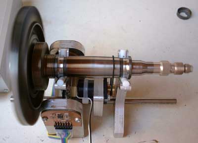
 This picture shows the
assembled rotor. The turbine wheel is shrunk to the shaft (via the hub). With brute force it is possible to separate the wheel from the shaft, which will be required for final assembly. Next will be balancing of the rotor,
firstly shaft with turbine, then the whole assembly. For this purpose I will have to arrange a special balancing setup. This will consist of two PTFE supports with V-shaped notches to guide the shaft, a piezo
transducer for measuring vibration and a tape-recorder type motor with belt drive to rotate the shaft. The required piezo signal amplifier probably will be equipped with a
schmitt trigger to allow for flashing of a LED to locate the heavy spot. The analog signal will be routed to a scope for qantitative analysis. Maybe a true-RMS multimeter could also
be used. If this setup works satisfactorily Ill post its design to an extra page on this site.
This picture shows the
assembled rotor. The turbine wheel is shrunk to the shaft (via the hub). With brute force it is possible to separate the wheel from the shaft, which will be required for final assembly. Next will be balancing of the rotor,
firstly shaft with turbine, then the whole assembly. For this purpose I will have to arrange a special balancing setup. This will consist of two PTFE supports with V-shaped notches to guide the shaft, a piezo
transducer for measuring vibration and a tape-recorder type motor with belt drive to rotate the shaft. The required piezo signal amplifier probably will be equipped with a
schmitt trigger to allow for flashing of a LED to locate the heavy spot. The analog signal will be routed to a scope for qantitative analysis. Maybe a true-RMS multimeter could also
be used. If this setup works satisfactorily Ill post its design to an extra page on this site.
Added 01/09/2001
The bearing retainer/seal is almost finished. I finally decided to repair this part as it would be quite difficult to machine it completely new. And now some pictures of this:
 This is what the damaged
component looked like as I disassembled the first Solent (this is a magnification from a larger picture, so please dont mind the poor quality).
This is what the damaged
component looked like as I disassembled the first Solent (this is a magnification from a larger picture, so please dont mind the poor quality).
The turbine wheel centering adapter burst out of the rear sealing shroud as the bearing disintegrated.
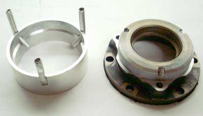 On the right you can see the
bearing retainer with all the damaged material spun away. The problem is that the space between the two sealing areas has to be pressurized with compressor bleed air to keep the oil from leaking to the
turbine wheel. These air ducts had been damaged, too, and thus needed restoration. The original part had been cast and was machined to size
afterwards. So I made a shroud out of aluminium that will form the rear labyrinth seal. The bleed air ducts are made of small aluminium tube segments, that are bent to give the
correct angle. It was quite difficult to get all this to fit perfectly together.
On the right you can see the
bearing retainer with all the damaged material spun away. The problem is that the space between the two sealing areas has to be pressurized with compressor bleed air to keep the oil from leaking to the
turbine wheel. These air ducts had been damaged, too, and thus needed restoration. The original part had been cast and was machined to size
afterwards. So I made a shroud out of aluminium that will form the rear labyrinth seal. The bleed air ducts are made of small aluminium tube segments, that are bent to give the
correct angle. It was quite difficult to get all this to fit perfectly together.
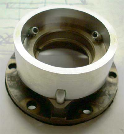 Here the components are
attached permanently with a special high-temperature compound. I also thought about shrinking, but this seems to be too difficult with all the tubes to match the bores. My experience with such things is that the
components to be shrunk will settle about half way together - and then youve got a problem ;-).
Here the components are
attached permanently with a special high-temperature compound. I also thought about shrinking, but this seems to be too difficult with all the tubes to match the bores. My experience with such things is that the
components to be shrunk will settle about half way together - and then youve got a problem ;-).
This part still needs some machninig for the outer labyrinth seal to fit correctly (when the compound has cured).
... still way to go to a working turbojet ...
Added 01/28/2001
Finally I got the new brass cages for the bearings from a friend of mine:
 Here one of the spindle
bearings is taken apart by cooling the inner race down to about -40°C and thus shrinking so it will eventually come loose. Above, sitting side by side one of the new brass cages and the old phenolic resin cage.
Here one of the spindle
bearings is taken apart by cooling the inner race down to about -40°C and thus shrinking so it will eventually come loose. Above, sitting side by side one of the new brass cages and the old phenolic resin cage.
 One of the bearings assembled
with the new brass cage, so it will be able to resist higher temperatures. Still some cleaning in hot oil will be required.
One of the bearings assembled
with the new brass cage, so it will be able to resist higher temperatures. Still some cleaning in hot oil will be required.
Added 05/03/2001
 After a long time with my other
projects I turned back to this one and balanced the compressor and turbine wheels (as displayed here and below).
After a long time with my other
projects I turned back to this one and balanced the compressor and turbine wheels (as displayed here and below).
Next will be grinding of the two graphite inserts for the main shaft oil seals, which have been damaged during the bearing failure. I expect this will be a really messy affair and hope that my vacuum cleaner will retain the carbon dust and not just blow it into the workshop.
 I also started removing the parts
of the intake nozzle casting that arent used any longer in this turbojet conversion. This is a really tough aluminium alloy and it took me more than an our of hard work with a metal saw to just get the larger parts off. Now
Ill have to ask a friend of mine to help me doing the fine work on a large lathe as this component wont fit on mine due to its diameter.
I also started removing the parts
of the intake nozzle casting that arent used any longer in this turbojet conversion. This is a really tough aluminium alloy and it took me more than an our of hard work with a metal saw to just get the larger parts off. Now
Ill have to ask a friend of mine to help me doing the fine work on a large lathe as this component wont fit on mine due to its diameter.
The next extension to this page hopefully wont take as long as this one...
Added 05/31/2001
 Today I finished the two graphite
rings for the labyrinth seals. This picture shows the compressor bearing retainer and the appropriate graphite ring. The difficulty when machining graphite is that it is very brittle. So I had to find a way to clamp
the material into the chuck of my lathe. This isnt possible directly so I machined a cylindrical aluminium stud that I glued the graphite to, using hot glue. Then
I machined the first face flat. The shape of the material was completely irregular as I had to saw the pieces out of a larger block that I got from Bene (Nicolas Benezan) - thanks a lot.
After heating the mounting stud and turnig around the graphite lump, gluing the now flat face to the stud, the rest of the machining was done. For machining I used my Dremel in the tool
holder (by the way of a special mounting attachement I made earlier) with a very sharp end mill of 3mm dia. And, of course a vacuum cleaner is required all the time when machining
graphite else the mess would be simply unbelievable.
Today I finished the two graphite
rings for the labyrinth seals. This picture shows the compressor bearing retainer and the appropriate graphite ring. The difficulty when machining graphite is that it is very brittle. So I had to find a way to clamp
the material into the chuck of my lathe. This isnt possible directly so I machined a cylindrical aluminium stud that I glued the graphite to, using hot glue. Then
I machined the first face flat. The shape of the material was completely irregular as I had to saw the pieces out of a larger block that I got from Bene (Nicolas Benezan) - thanks a lot.
After heating the mounting stud and turnig around the graphite lump, gluing the now flat face to the stud, the rest of the machining was done. For machining I used my Dremel in the tool
holder (by the way of a special mounting attachement I made earlier) with a very sharp end mill of 3mm dia. And, of course a vacuum cleaner is required all the time when machining
graphite else the mess would be simply unbelievable.
Now the components for the engine core are finished so far that it could be assembled. I will do a lot of cleaning prior to this, especially the fine oil galleries in the bearing tunnel need to be free of any dirt or dust.But I think I will put it togeter one of the next days and I hope things will become a little bit more exciting then...
Added 06/12/2001
 Finally the high-temp glue
(Loctite 648) I used to assemble the graphite rings in the shaft tunnel seal plates cured and I continued assembly of the engine core. Upon the first try to mount the turbine wheel the outer (air)seal collar turned out
to be slightly too tight resulting in heavy rubbing of the turbine wheel air seal. After disassembly I spun off another 1/10mm in diameter and that fixed the problem. I hope the air leakage through this seal now
isnt too large, but this will show later.
Finally the high-temp glue
(Loctite 648) I used to assemble the graphite rings in the shaft tunnel seal plates cured and I continued assembly of the engine core. Upon the first try to mount the turbine wheel the outer (air)seal collar turned out
to be slightly too tight resulting in heavy rubbing of the turbine wheel air seal. After disassembly I spun off another 1/10mm in diameter and that fixed the problem. I hope the air leakage through this seal now
isnt too large, but this will show later.
 The turbine wheel is finally
assembled. It fits snugly into the integral NGV turbine shroud, leaving a gap of approx. 0.3mm. Seems as it was made to go there, and thats not quite obvious after all the machining I have done ;-).
The turbine wheel is finally
assembled. It fits snugly into the integral NGV turbine shroud, leaving a gap of approx. 0.3mm. Seems as it was made to go there, and thats not quite obvious after all the machining I have done ;-).
In the foreground sits the special crown wrench I had to make to tighten the turbine and compressor nuts to the appropriate torques. I had to file the crown and I can tell this wasnt fun at all (...blister on thumb and all those nasty things...).
The cupwashers arent crimped yet to secure the shaft nuts. Ill probably do this after the turbine completed its first run (if it runs at all) and I have re-tightened the nuts.
 The engine core as seen from
the compressor end. Im glad I finished this assembly so far. Next will be sandblasting of the outer casing and the intake section. Then Ill have to disassemble the nozzle ring to clean all eight fuel nozzles and
set the opening pressure approximately to equal values to allow for more even combustion at lower power settings.
The engine core as seen from
the compressor end. Im glad I finished this assembly so far. Next will be sandblasting of the outer casing and the intake section. Then Ill have to disassemble the nozzle ring to clean all eight fuel nozzles and
set the opening pressure approximately to equal values to allow for more even combustion at lower power settings.
Yet Ill have to ask a friend of mine to help me machining the intake on his large lathe to remove some of the material that is no longer needed for engine operation as a pure turbojet.
I cant wait to do the first start attempt. It will probably scare the hell out of me, Ill only need to remember the first runs of my turbocharger engine. And this one will give five times the turbos troughput.