The Story Continues - Already Three Ultrasport 496T Flying!
14.06.2009 - Itís been a long time since my last contribution to my web site, and many things have happened since. Most important (for me...) is that in
february this year my daughter has been born and as a consequence, priorities changed a lot. Yet, I also continue my work on turbines, but what Iím doing right now hasnít developed far enough to be released to the public...
Yet, other turbine-related projects already bear fruits:
Last year, my friends Platon and Andreas, and myself in a collective effort designed and constructed a new custom gearbox/clutch system to bolt directly onto the
Ultrasport 496 at one end and accomodates the Solar T-62T-32 engine at the other. We adapted a very clever coaxial centrifugal clutch configuration that I already suggested to Platon when we met the very first time probably
five years ago. Meanwhile, Platon converted another two 496ís to turbine power, one in Thailand and another in his own hangar on the island of Cyprus, for an owner in Germany. I assisted him with these conversions by doing most
of the electrical stuff and I also designed a new ECU with much improved safety features, an important thing if youíre going to use an engine that is electrically controlled.
Last week I once again spent on Cyprus since
Platon asked for my help on sorting out a few electrical problems on his own helicpter that heís converting to the latest production systems. We also wanted to finalize the ECU software since during the last two conversions, we
never had enough time to dedicate to the software issues, so these helicopters are running on a somewhat preliminary version which is safe but not as elaborate as it could be.
The New Gearbox Centrifugal Clutch Assembly:
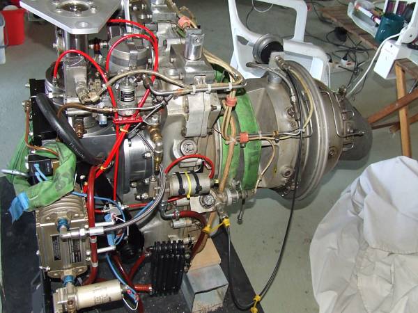
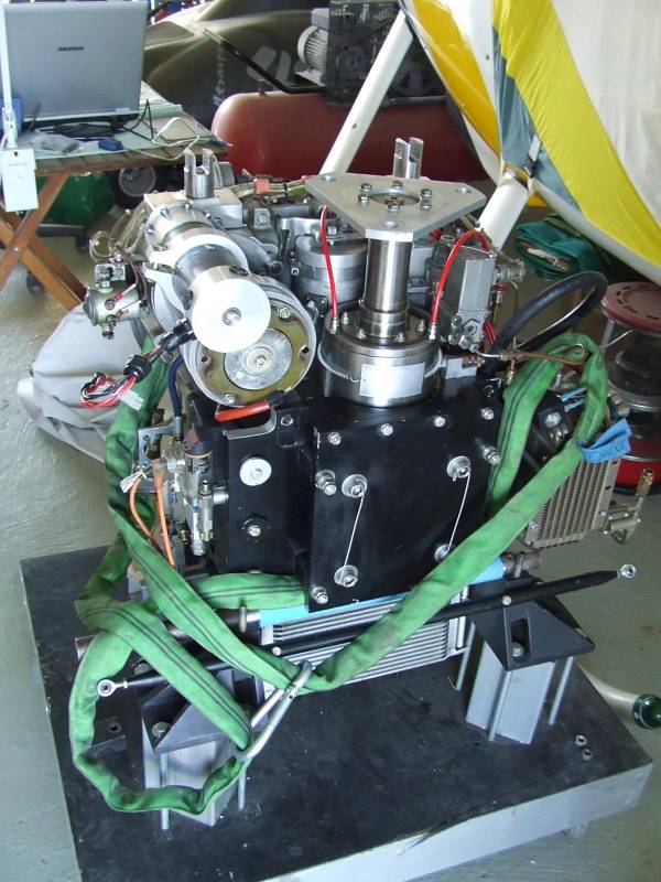
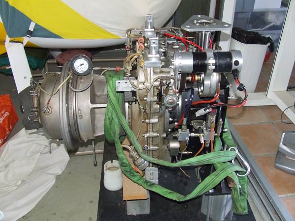
First, let me show and explain you the arrangement of Platonís prototype system that he used for probably almost a hundered hours on his own 496.
 |
 |
 |
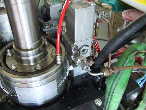 |
Platon used a stock Solar T-62T-32 enigne like many enthusiasts do to convert their helicopters. The engine itself is a reliable and forgiving design with a few but livable shortcomings. With about 60kg itís quite heavy and itís also a thirsty beast since itís pressure ratio as well as the turbine entry temperature are low. The ďupĒ side of this consequently low thermodynamic efficiency is a long service life of the machine. Platon adapted a (more or less) of-the-shelf bevel gearbox with a reduction ratio of 2.5:1 (made by Tandler, Germany) to the engine drive pad and put a hydraulic multi-disc clutch on the output side of this gearbox (shown in the photo above). This attangement was chosen to have the engine in the most forward position possible for centre of gravity (CoG) reasons. The disadvantage of this arrangement is that the clutch will have to trasmit a 2.5 times higher torque than if it was placed between the engine and the bevel gearbox. Moreover, the hydraulic clutch requires hydraulic pressure to be present as long as it is supposed to be engaged. A loss of hydraulic pressure causes immediate disengagement of the clutch. Platon used a clever arrangement of check valves and a re-pressurizing pump, connectd to an electronic pressure transducer and a small servo electronic unit that I converted from one of my other projects for him. This would gradually engage the clutch after the engine has reached a certain RPM and the clutch engagement switch has been pressed. Yet, clutch engagement was very quick and left the pilot little time to find the ďsweet spotĒ on the cyclic. Another issue was that the gear reduction ratio was not the optimum match for the engine would run around 94% of its design RPM to reach 100% helicopter rotor speed. This doesnít sound much but a turbine engine, especially if itís single spool like the Solar, loses power quickly if operated below its design speed. At 94%, I would expect the engine to lose about 20hp (then producing 130hp instead of its rated 150hp). Actually, these engines can be considered to be single speed devices. The power output is only controlled by increasing/reducing torque while RPM stays constant. But thatís exactly what you want on a helicopter, a rock-solid rotor RPM while you can pull the collective and donít have to worry about the effect on the engine.
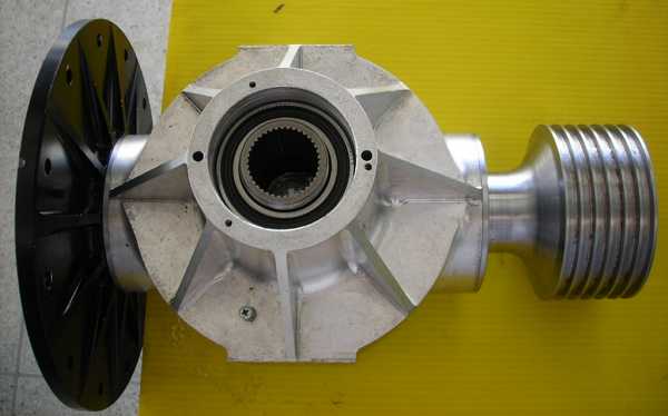
All these issues finally led us to the decision that a custom-built gearbox/clutch assembly is the only way to go. In late 2006 I did some calculations and ended up with a preliminary design that we finally refined to what it is today. And hereís what it looks like (click the picture for a large-scale TIFF version):
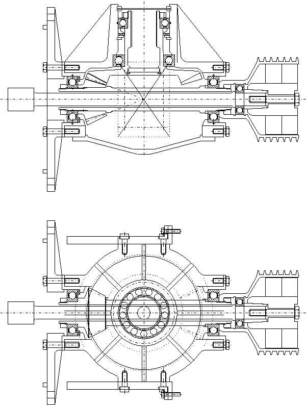 |
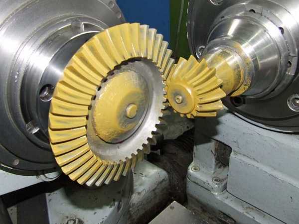
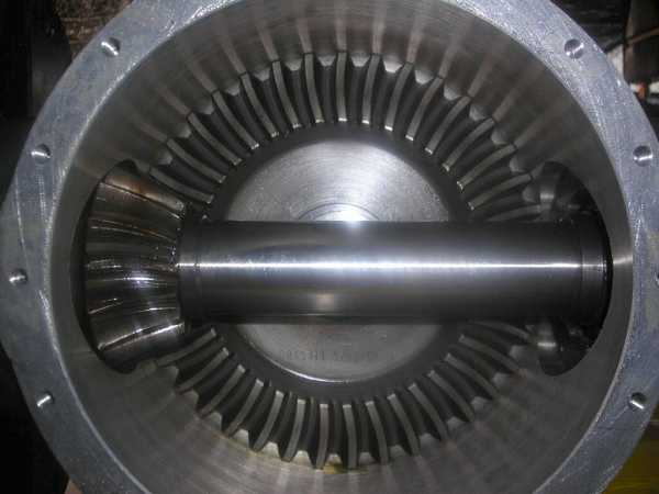
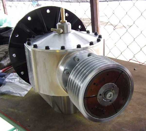
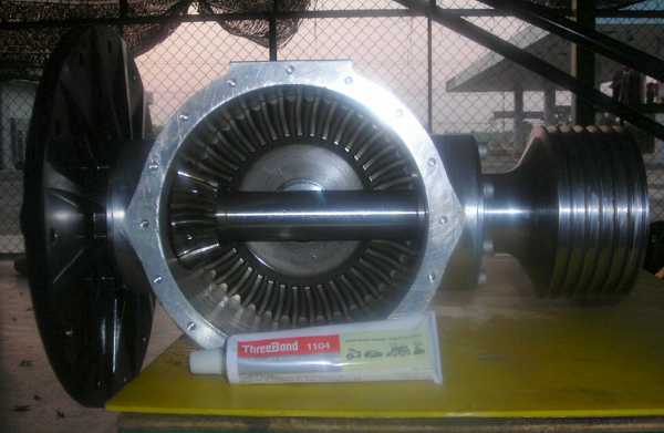
At the left side, the engine will be bolted to the mounting flange, driving the long central shaft. This shaft goes right through the hollow pinion drive shaft to the opposite end of the gearbox. Here the central shaft is suspended by a single, sealed ball bearing inside the ďbellĒ of the centrifugal clutch. At the far end of the central shaft, the centrifugal clutch, a hex flyweight version, arranged in two planes, was used. Below engagement RPM, the central shaft with the flyweight assembly is free to rotate inside the hollow pinon shaft while its considerably large free length will conpensate for small radial alignment tolerance between engine and gearbox. Once engaged, the central shaft and the hollow pinion shaft will rotate at the same RPM, transferring the torque to the upper gear which rotates at a ratio of approx. 2.65:1. I calculated the shaft resonance speeds of the central shaft with the clutch free-running below engagement RPM and the central/hollow shaft ensemble above engagement RPM and luckily found that neither was in the operational RPM range of the gearbox. Then I identified a company that would be qualified to manufacture the gears for us (Graessner, Germany), and Andreas finished the manufacturing drawings. The price for the gears was reasonable, so they got the job. Well, someone among us must have made a mistake not to have negotiated a fixed date of delivery with Graessner, and the time passed quickly. First, the gears were supposed to be finished end of 2007 but january 2008 came and no gears to be found anywhere... Platon already got a client for a helicopter turbine conversion but fortunately he understood the situation and that we couldnít change it. Finally, there was another conversion on a helicopter located in Thailand scheduled, and Platon already spent there several weeks, doing initial work since this certain machine needed a complete check-up. We had some serious talk with Graessner and after several passed dates, they finally promised to deliver on 6th of june 2008. I booked a ticket to Thailand on 7th. Andreas and I personally went to the Graessner company to make absolutely sure nothing will go wrong anymore. And this time, really everything went well. Our contact partners at Graessner were very helpful and showed us in every detail how to align the gears. Since the gears are of the Gleason Cerol type, their intermeshing pattern can easily be made visible with some chalk suspended in grease. Alignment turned out to be less difficult than I thought (shown in the next photo). So finally the quality of Graessnerís job was okay, let alone if they had delivered sooner, things would have been much more relaxed. The next photos show the gears and the whole assembly.
 |
 |
 |
 |
 |
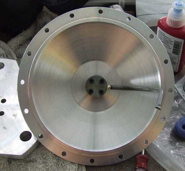 |
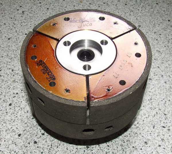
This last photo actually shows the lower gearbox cover with the integrated lube oil feed pipe and drain assembly. Itís sealed with a radial O-ring gasket. This cover also improves the mechanical rigidity of the gearbox. Thatís why we used so many bolts to mout it. And hereís our clutch:
 |
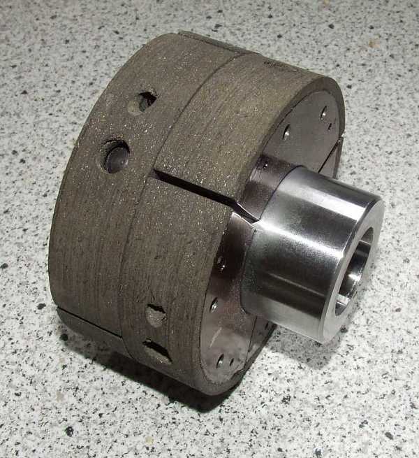 |
The clutch later on caused us some headache. Firstly, it tended to engage at too low RPM so with the engine idling at 40%, it already started gripping. Later, the return springs mounted tangentially between two adjacent flyweights, just fractured. Initially we really didnít have the slightest idea what caused this, but later I started doing some calculations on the springs the manufacturer used. To my surprise, they turned out to be overloaded already before the flyweights even started to move! Fortunately, there was sufficient space to mount other springs that I calculated and had specifically made by a spring winding company. Platon also re-drilled the holes for the spring mounting pins to be able to put in stronger pins. This did the trick; now weíve got a slightly higher engagement RPM (the clutch just starts to grip at 45%) and we never had a spring failure since. Even though a broken spring isnít a safety problem once flying, itís quite a nuisance since the engine cannot be started anymore with a single broken spring. Fortunately, access to the clutch at the front end of the gearbox could be worse.
The ECU:
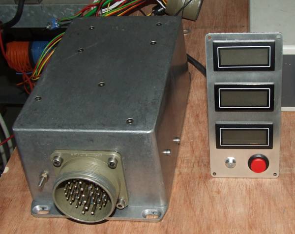
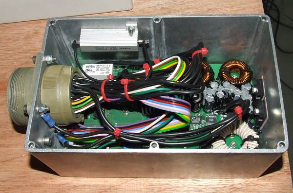
The electronic control unit for the engine is something that Iím mighty proud of. Even though now itís just an ugly cast aluminium box with a single 32 terminal MIL style connector, itís a giant leap forward compared to the prototype arrangement that we used on Platonís machine before. Here are some photos, even though they donít explain too much.
 |
 |
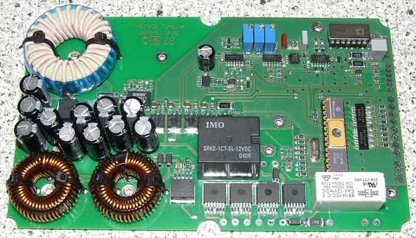 |
This last photo shows the PCB of the ECU before the wires are soldered in and itís mounted
inside the aluminium box. You may click the photo for a higher resolution version.
The ECU actually consists of a combination of the control panel and the ďintelligentĒ electronics
itself. Iím using a PIC16F876A microcontroller as the ďbrainĒ of the system (and not the ancient PIC16F73 shown above, but the gold plated, windowed ceramics DIP looks so much more
ďimportantĒ, so I just had to insert it for this photo...).
Here's a short list of the features of the ECU:
- specifically designed for the Solar T-62T-32 engines
- controls all the engine systems and monitors its functions
- includes governor (RPM stability appr. +-0.5% no-load / full-load), startup sequencer, safety monitoring systems
- internal data logging of the last 30 minutes of operation as well as total run time and startup cycle counter, data can be retrieved by a special RS232 interconnection adapter onto a PC (yet to be implemented...)
- post-shutdown status indicator to show the reason for a "red light" (if any) during engine operation
- optional 12V back-up battery can be attached so the engine will be kept running if main power
fails, backup battery is recharged during normal operation
- operates from 12V to 28V, maximum current consumption during startup 25A, during normal
operation approx. 5A; during starter engagement supply voltages as low as 4V will be tolerated
- internal, electronic RPM preset pot to eliminate long, RFI-sensitive and safety-critical wires as
well as failure-prone mechanical pots
- control panel is equipped with three back-lit LCDs to show preset RPM percentage, actual engine RPM percentage and EGT in degrees celsius (can be modified to display farenheit), one
momentary "start engine" switch and an ultrabright two-colour LED indicator to indicate engine status
- connections for rpm trim up, rpm trim down and "kill engine" momentary switches
- up to four auxiliary inputs for pressure or temperature switches or chip detectors (to be software configured if required)
- RFI insensitive optocouplers on all external connections
- hermetically sealed aluminium enclosure, Cannon MIL style connector
- ECUs will be pre-adjusted to work directly, without additional adjustment, on any stock T-62T-32
engine with an aftermarket 12V starter (original starters will also work if a 24V power system or external 24V supply is used)
- Using SMT throughout the circuitry for much improved susceptibility to vibration
The software so far implements many features of which a few I would like to highlight:
- startup sequence improved so the main fuel valve will be opened only if thereís an EGT reading higher than 100įC and not only based on the RPM schedule as specified by Solar. This prevents the engine from being flooded with fuel in case of a delayed light-off. It will also keep the start fuel pressure high for good atomisation until the engine actually lights off. This improves cold climate startups considerably
- engine acceleration and clutch engagement controlled by an EGT schedule. If the temperatures during engine acceleration (between 40% idle and 80% start fuel valve disengagement RPM) should approach the limit of 600įC, further increase of RPM preset will be inhibited. If EGT increases further, the ECU will actually decrease RPM preset to bring temperatures down again. If all this wonít help, the engine will be shut down to prevent it from damage.
- this shutdown feature is only enabled during startup and acceleration. in ďRun ModeĒ, i.e. the helicopter is potentially flying, the pilot is responsible to decide about engine health. The electronics will only light a warning signal if thereís a malfunction detected. This may leave the pilot valuable time with engine power available, even if the engine later may be a smoking heap of melted metal...
- during ďRun ModeĒ, thereís one single situation that indicates for an engine shutdown, thatís too high or erroneous engine RPM. As per the Solar specifications, the limit is set to 110% rated speed. If, for some reason, the engine will reach that speed, then the governor isnít in control of the engine anymore, either due to mechanical or (rarely) due to electrical failure of a component. The result of a run-away situation is much more dangerous than a forced autorotation. If the engine accelerates without limit, the rotor system of the helicopter may be overloaded and fail or the turbine rotor may explode and cause severe damage to components in its neihbourhood, potentially making an autorotation impossible. A failure of the engine RPM pickup will have the same result because the engine cannot be controlled anymore if there isnít a reference signal available.
- if the engine is operating in ďRun ModeĒ and the ECU senses a fast decrease of RPM or EGT, it will energize the ignition exciter. In case the change of RPM or EGT was caused by a flameout, thereís a good chance that the engine will relight and return to normal operation. Even though I never witnessed a T-62T-32 with a properly adjusted fuel control unit (FCU) to flame out, this may give the pilot some additional peace of mind...
- the hardware of the ECU is prepared to implement data logging functions, but so far there wasnít enough time to implement them in software. Thatís still something on my ďTo-Do-ListĒ...
By the way, hereís a short write-up of the pros and cons regarding an electronic fuel control system, especially emphasizing the Solar enigne when used on experimental aircraft. Actually, just my own thoughts but as I think with a good amount of common sense.
Now some photos of the two previously converted helicopters follow, the first four of the Thailand machine, located close to the city of Narkhon Ratchasima (aka ďKoratĒ).
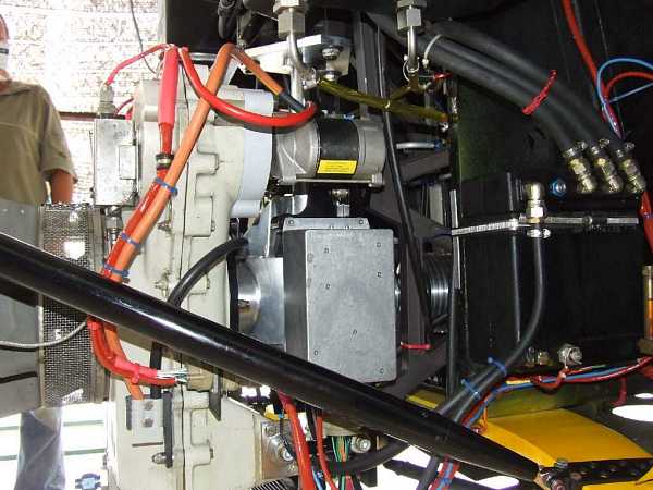 |
The new installation is a lot cleaner than the prototype...
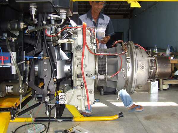 |
Our friends from Thailand are eager to learn.
 |
Platonís doing some adjustments
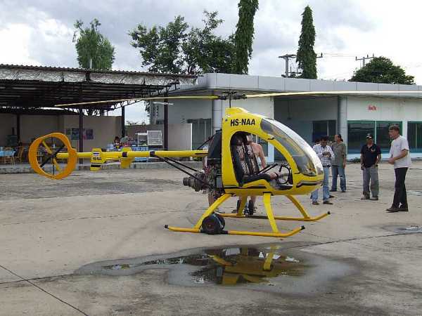 |
Almost ready to run... Yet, vibrations in the tail rotor/drive system still caused some delay. Eventually, the problems were sorted. Now the helicopter is flying well and during the test flights which took several hours every day for about two weeks, our test pilot Mark gave the locals the opportunity of a trip over their area on the co-pilotís seat. Of course, this was gladly accepted and for many probably an unforgettable experience...
The following two photos are courtesy of Johannes Ernst of Germany, the owner of the second series conversion helicopter. Please click the photos for a link to his web site (German language).
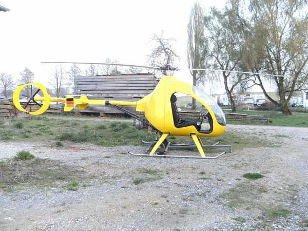 |
Thatís a nice, clean machine. It appears the turbine engine was just meant to go in there...
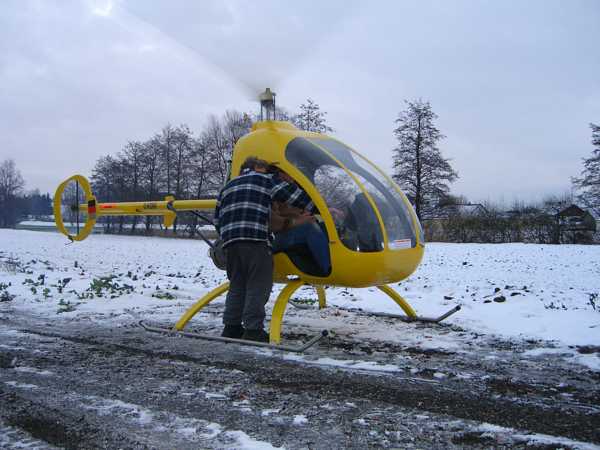 |
Platonís instructing Johannes about the specifics regarding the turbine. As you can see, itís the winter season in Germany. Platon came with our good friend Marios from Cyprus and they didnít expect to meet snow and temperatures well below zero. Johannes offered them long, warm pants so they wouldnít catch a cold. Marios refused, he would never put anything like this on... Of course, after they went outside, it was just a matter of minutes that he changed his mind... ;-). Now, they both use to have a good laugh about this episode and at least, they know what long pants are good for!
Well, thatís more or less what happened during the last two years. You see, Platon evolved his prototype design into a safe and reliable series modification that will change the underpowered, original 496 into a completely different, much more reliable and versatile machine, the 496T.
My Recent Trip to Cyprus, 1st to 8th June 2009:
Actually I was quite happy that I was leaving towards Cyprus because the weather in Germany wasnít too good these days, especially considering it was already june! My daughter and my fiancee are still in Moscow and my visa is only valid again in three weeks, so I cannot visit them anyway during these days. In future, when they will stay in my place with me, Iíll probably think differently about easily going to another place for eight days...
After a nice, calm flight to Larnaca with some very peculiar views of the landscape due to the setting sun, I arrived in Cyprus on Monday evening.
 |
Reflection of the mountains around Antalya, Turkey in the mediterranean. Quite a peculiar sight!
 |
On our approach to Larnaca airport. The arrow indicating the location of Platonís hangar.
Platon picked me up at the airport and we went to his flat to meet his wife Maria and his youngest son Taki. I sorted my luggage so we had one bag with stuff for the hangar while I took my suitcase with the remaining things to the hotel where I always use to stay, just a walk of two minutes from Platonís flat. Like every night, Maria prepared a very nice dinner for us. We decided to have an early start next morning so I could get a first impression of the situation and what would need to be done. This might have given us the chance to have some afternoons off during the last days of my stay, we thought... ;-).
Okay, here are some photos of the initial work and the set-up in general.
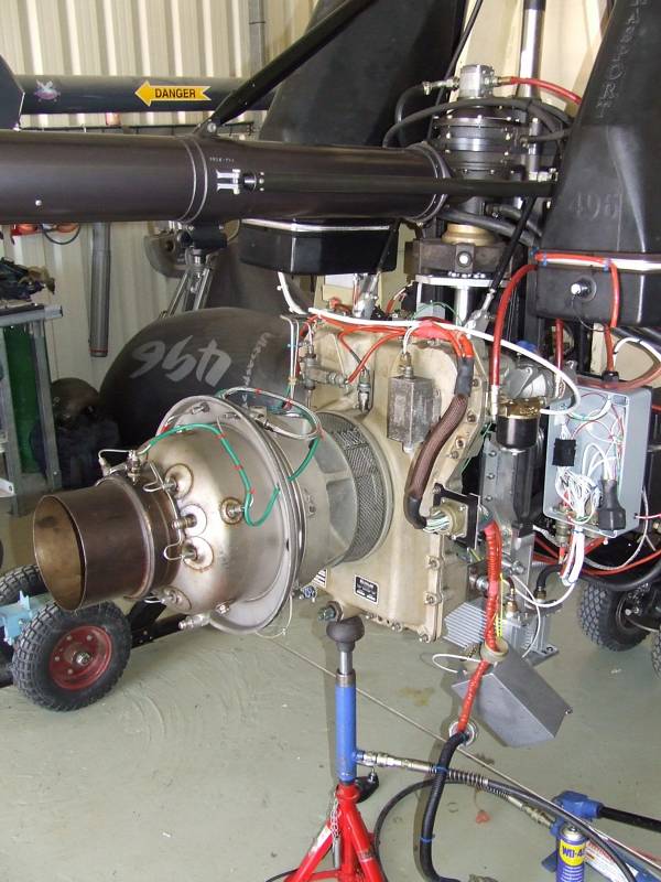 |
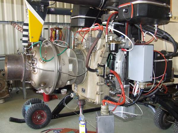
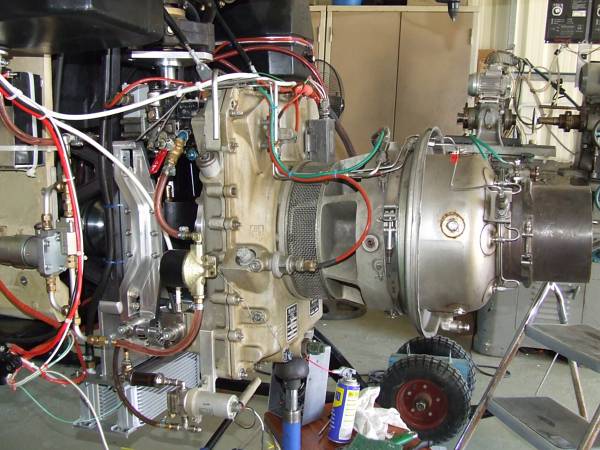
Platon already finished the complete mechanical installation of the engine and also prepared the wiring. Yet, the electrical System was working erroneously.
 |
 |
 |
 |
 |
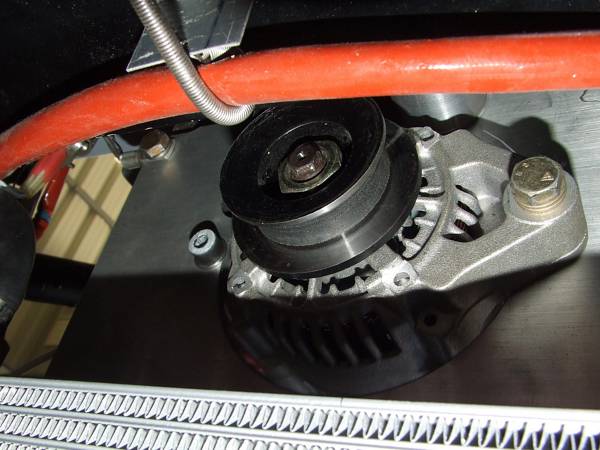 |
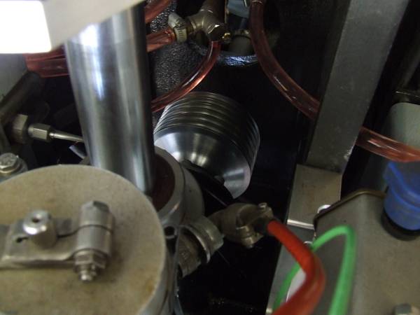
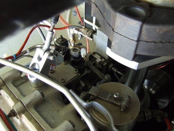
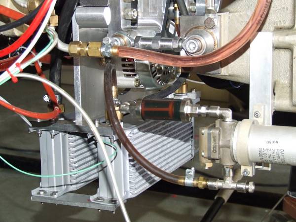
Some more details of the mechanics, everything done to the highest standards. Here the alternator, mounted beneath the gearbox, is shown. Itís driven by a flat belt from the cylindrical part of the centrifugal clutch ďbellĒ. So the alternator wouldnít load the engine during startup. Thereís a switch located on the dashboard to electrically engage the alternator via a powerful relay. This is done in order to keep additional load on the engine as low as possible while the clutch engages at around 45% RPM and the helicopter rotor system is accelerated. At 60% engine RPM, there is enough power available to carry the load of the alternator.
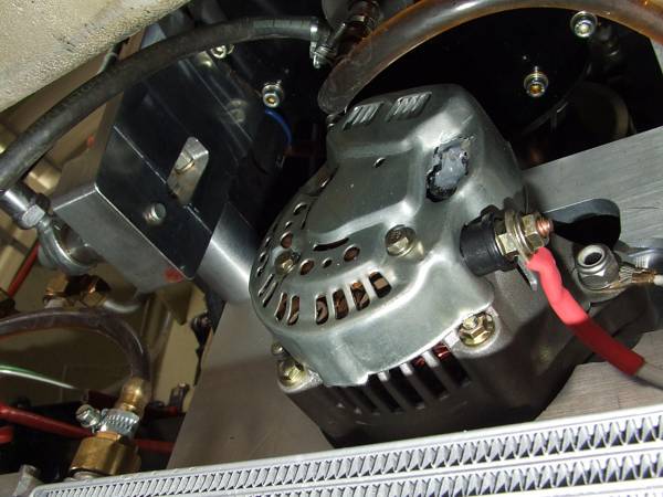 |
...the right alternator mounting bolt should be replaced with a longer one... ;-)
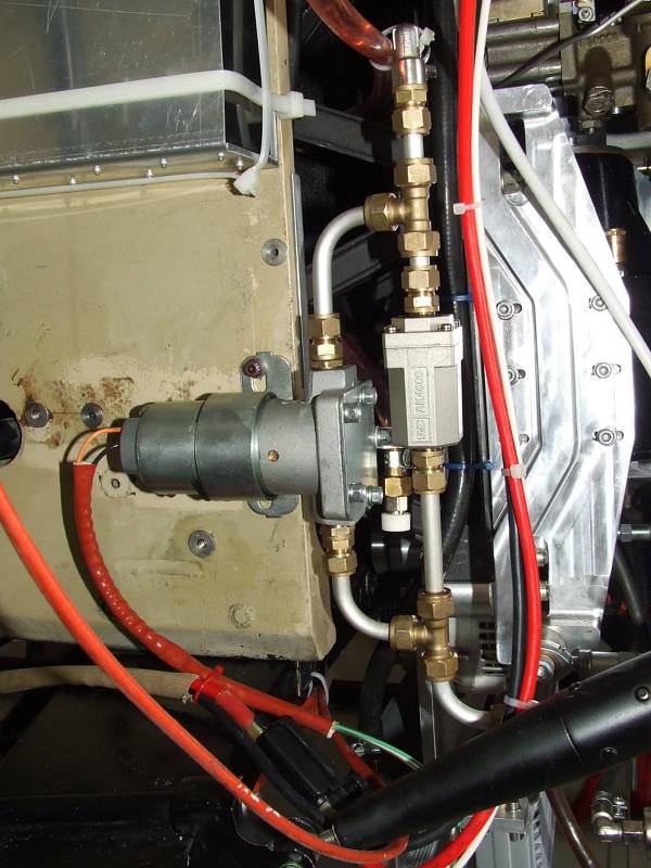 |
Thatís the fuel boost pump, bypassed with a check valve with a very low crack pressure.
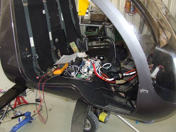 |
Thatís what it looks like when I start my work...usually it gets messy ;-). We had a very peculiar short of two adjacent contacts in a connector. What actually caused the problem, we never found out. We just decided to replace the whole connector with a MIL style version...
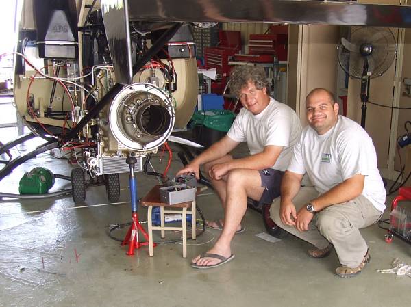 |
Platon and our friend Marios who came all the way from Paphos almost every day to lend us a hand. Heís also preparing to build a helicopter, probably as well powered with a T-62T-32.
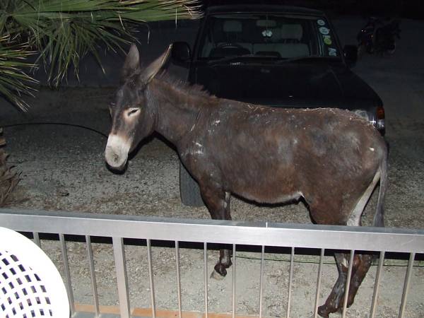 |
A nightly visitor, also interested in helicopters. Unfortunately we couldnít offer him a ride since he wouldnít fit into the helicopter. Next time Iíll bring my MI-26 and he can bring some friends... ;-)
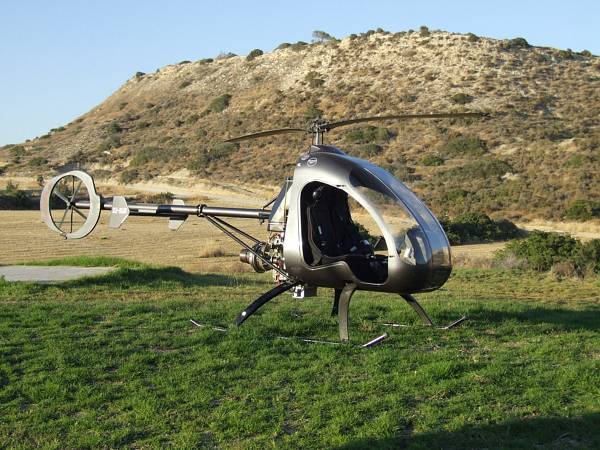 |
Platonís helicopter, finally assembled and taken outside for the first tests with the rotor system attached to the engine drive shaft. We did several test runs of the engine/clutch/bevel gearbox system inside the hangar and I optimized the software of the ECU considerably. Yet, during the first attempt to accelerate the rotor, at about 80% engine RPM, Platon noticed a loss of power and we also found the EGT to decrease. Thatís clearly an indication of starvation of fuel so we had to take the helicopter back inside to analyze the problem. Since it was already evening and all three of us were a little bit disappointed, we decided to continue the next morning. Since Platon used an engine for this set-up that he never ran before, I suggested to replace the complete FCU with another one thatís known to be good.
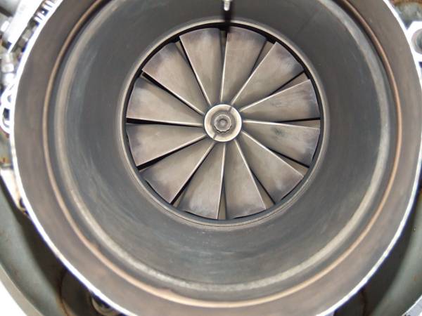 |
Donít get me wrong, the engine that he used was in decent condition as you can see from this shot of the ďbusiness endĒ, and also the bearings show no wear or abnormal play, but itís also obvious that it has already been runnnig for some time.
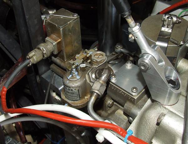 |
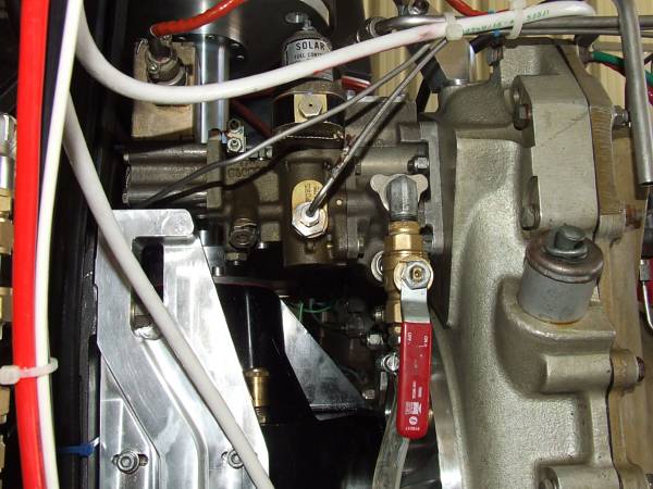
So the next morning, we arrived at the hangar in good mood again and with fresh energy. While I did some more programming and optimization of the ECU code, Platon removed the engine from his helicopter to replace the FCU with this brand-new unit that he returned from the Thailand machine where he had it as a spare. After I finished the ECU stuff, I decided to have a look at the removed FCU to understand the reason for the problems that we encountered the day before. Actually, we can thank God that the problem occured already during acceleration and not during an actual flight. Though I didnít yet finish diasassembly of the FCU when Platon had the helicopter back together, we decided to test run the engine before we found the reason for the failure. Since alignment of the throttle control shaft/lever is always a little bit awkward on the Solar FCU, I was aware that we may have to expect anything from the engine not lighting off to a run-away situation without the ability to control RPM. So during these ďfirstsĒ someone always has to have his hand on the fuel shutoff valve (see below).
 |
Sure enough, the engine didnít light off. Nothing to worry so far, just align the control shaft vs. the lever a little more towards the ďopenĒ position. But again, the engine wouldnít ignite. We also didnít find any fuel to flow from the start fuel nozzle. We expected the start fuel solenoid valve may be faulty on the new FCU and opened the main fuel line just before the main fuel valve to see if we got fuel from there. Actually, we found some fuel to drip from there all the time, regardless if the engine was motored or not. That was very peculiar and I never saw anything like this before. I told Platon in my opinion this could only be the result of either the high pressure pump in the FCU being defective or the pressure limiting valve for some reason being stuck open. We had no choice but to remove the FCU again. Since removal of the engine takes a long time, we checked for other options and found that even though thereís little space available, we might be able to split the FCU at the flange between high pressure pump and the acceleration limiter valve body. We actually got half of the FCU out of the installation this way and continued with removal of the pressure limiter valve.
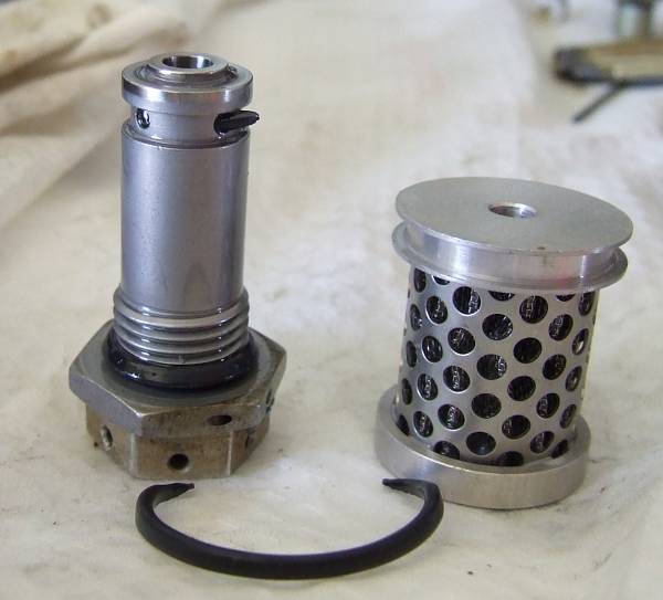 |
You should have seen the amazement on our faces about what we found there. It turned out that somebody must have removed the fuel filter inside the high pressure pump body and upon reassembly, the O-ring that seals up- and downstream of the filter, had been sheared. Since the separated part of the O-ring ends up downstream of the filter, it will eventually be washed away with the fuel into the control section of the FCU. Sure enough, we found the missing part stuck in the pressure limiter valve, locking the control piston in the open position.
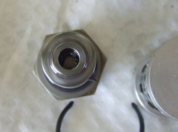 |
Fortuantely, the two parts of the O-ring matched exactly and so we could be sure that there wasnít anything left in another place inside the FCU. Yet, we learned from this that ANY Solar FCU, regardless form what origin, needs to be disassembled and checked for cleanliness before it is put on an engine in an experimental aircraft. At that time, all the O-rings should be replaced with new ones as well. Actually, we found a smaller piece of a shaved O-ring in the same position in the other, first FCU...
The start attempt following reassembly was successful and after some adjustments of the FCU, we were happy with the setup. I recorded a few videos of what came next, so have a look if you please:
This one shows a start of the engine inside the hangar. Actually, you donít see much except the turbine wheel spinning. But this shows how well the system is working and how far advanced the ECU is. No smoke, flame or anything is visible while the engine accelerates happily in about seven seconds to 40% idle speed and stabilizes there.
Here we already moved the Helicopter outside again. Basically, the engine control panel is shown and how quickly the engine starts by just pressing a single button while the ECU takes care of everything else. The top instrument displays engine RPM, the centre one preset RPM (can be trimmed up/down with the RPM trim switch located on the cyclic stick) while the lower instrument reads EGT in degrees centigrade.
The next video is very short and just shows the engine running at round about 60% with the clutch already engaged. Once again, you see that you donít see much ;-). No smoke at all, just an engine happily sipping fuel...
And finally, all systems had been checked and re-checked and despite the very gusty conditions this early afternoon, Platon decided to take the helicopter to a low hover. He waved me two times to look at the panel since the engine relight indicator came on frequently, probably the RPM/EGT drop detector was programmed too sensitive. After he put down the helicopter again, he experimented a little bit with the throttle authority and tested if it would be possible to purposely cause a flameout of the engine. It wasnít...call it a SUCCESS!
 |
Unfortunately, I had to leave this evening, yet not without recording a nice panorama of Platonís place. Iím sure it wonít be too long until I will return, maybe to help Platon with his next father/son project, mybe to assist Marios with the electrical stuff to get his own helicopter running. Platon will still hover his helicopter for a while at low altitude until a reasonable ďshakedownĒ period has passed before he will eventually take it higher and more far out above ďhisĒ valley on Cyprus.
 |
Thanks for reading and good night!