Electric starter for KJ66 and similar Jet Engines
Since business is a little draggy these days I decided to build my own electric starter for my Behotec model aircraft turbine engine rather than buying a ready-to-use one. If I take the time into accout that it took to make the starter so far, it definitely isnt a bargain. But if this were a concern, I would probably have chosen watching TV as a hobby and not gas turbine engines...
I still had a suitable DC motor available from another project. It is of the Speed 300 size but its a Sagami brand with a lot more power and ball bearings. If I remember correctly Multiplex sells these motors (brand name: Permax 280BB). I also didnt want to have the whole clutch mechanism suspended on the motor bearings alone because I heard of some fellow enthusiasts having problems with shaft resonance at high speeds due to the relatively thin motor shaft and the considerable weight of the clutch mechanism attached to it. So I decided to use two additional miniature ball bearings to support the clutch engagement shaft directly. And here are some pictures of the components:

On top theres the motor, below from left to right: Starter case, Clutch member with engagement helix, M2.6 screws that bolt the case to the motor, clutch O-ring (a different one will be needed when the starter is attached to the engine), clutch engagement pin (in the centre of the O-ring), two bearing spacers, motor shaft extension and two 9mm*5mm*3mm (od*id*width) ball bearings.
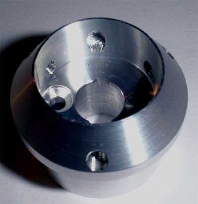 Heres a closeup of the starter case.
This component required quite some machining work. It doesnt only adapt the starter motor to the turbine intake but it also aligns the additional bearings with the motor shaft and the shaft extension. Thus it needs to be
made to very high precision, especially the surface that seats the bearings.
Heres a closeup of the starter case.
This component required quite some machining work. It doesnt only adapt the starter motor to the turbine intake but it also aligns the additional bearings with the motor shaft and the shaft extension. Thus it needs to be
made to very high precision, especially the surface that seats the bearings.
 Here the moving clutch member is
shown. You can clearly see the helix that is milled into the guiding area of the bore. This helix was milled on a four-axis CNC mill. Theres certainly another way to machine the helix with more common tools but since Ive got
the mill, why shouldnt I use it ;-) ?
Here the moving clutch member is
shown. You can clearly see the helix that is milled into the guiding area of the bore. This helix was milled on a four-axis CNC mill. Theres certainly another way to machine the helix with more common tools but since Ive got
the mill, why shouldnt I use it ;-) ?
The bore just left to the recess accepts one end of the recoil spring. I considered using a magnet to hold the clutch in the withdrawn position when the starter is not in use, but this would have meant glueing a magnet and a ferromagnetic backplate to the starter components and I just didnt feel too well with this idea. Especially as there arent many adhesives that will reliably stick to aluminium.
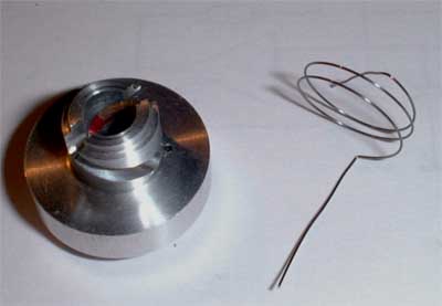 Here you see the clutch member
again as well as the recoil spring. I made this spring from 0.25mm diameter steel spring wire. One end sticks through the bore in the clutch member and is just bent around on the other side to keep it from slipping
back. The other end projects through a concentric bore in the clutch engagement pin that is located in the extension shaft. This way the spring will always exert a small torque on the clutch member to hold it in the
withdrawn position. Yet the torque is low enough to allow the motor to engage the clutch when it accelerates rapidly.
Here you see the clutch member
again as well as the recoil spring. I made this spring from 0.25mm diameter steel spring wire. One end sticks through the bore in the clutch member and is just bent around on the other side to keep it from slipping
back. The other end projects through a concentric bore in the clutch engagement pin that is located in the extension shaft. This way the spring will always exert a small torque on the clutch member to hold it in the
withdrawn position. Yet the torque is low enough to allow the motor to engage the clutch when it accelerates rapidly.
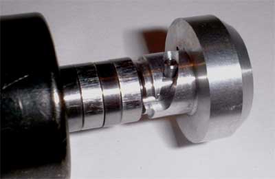
 Heres the motor with the shaft
extension pressed in place. The motor itself has got a corrugated shaft of slightly less than 2.0mm diameter. So drilling of a truely concentric hole in the shaft extension that will accept the
motor shaft with a press fit wasnt easy you bet. It took three attempts to get it finally right. The bearings and the spacers are in place as well, as is the clutch engagement pin. This pin is
glued in a bore in the shaft extension with Loctite 648. This way it should never come out if it isnt forced to. The bore through the pin is also visible, here one end of the recoil spring will be located.
Heres the motor with the shaft
extension pressed in place. The motor itself has got a corrugated shaft of slightly less than 2.0mm diameter. So drilling of a truely concentric hole in the shaft extension that will accept the
motor shaft with a press fit wasnt easy you bet. It took three attempts to get it finally right. The bearings and the spacers are in place as well, as is the clutch engagement pin. This pin is
glued in a bore in the shaft extension with Loctite 648. This way it should never come out if it isnt forced to. The bore through the pin is also visible, here one end of the recoil spring will be located.
 The clutch mechanism is preliminarily
assembled to check its working smoothly and without binding. Everything looks nice so far and final assembly is getting closer...
The clutch mechanism is preliminarily
assembled to check its working smoothly and without binding. Everything looks nice so far and final assembly is getting closer...
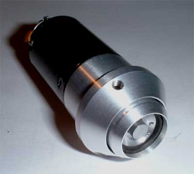 And thats what the finished starter
looks like (so far...). Ill still need to make a cover for the whole assembly, but thats just for the look of it. Ill probably use black POM plastics for this cover since thats light-weight,
easy to machine and it looks quite nice. The starter works very well so far, the clutch flips in and out very quickly and should really be up to the task. Next will be adapting the turbine intake section to accept the starter.
And thats what the finished starter
looks like (so far...). Ill still need to make a cover for the whole assembly, but thats just for the look of it. Ill probably use black POM plastics for this cover since thats light-weight,
easy to machine and it looks quite nice. The starter works very well so far, the clutch flips in and out very quickly and should really be up to the task. Next will be adapting the turbine intake section to accept the starter.
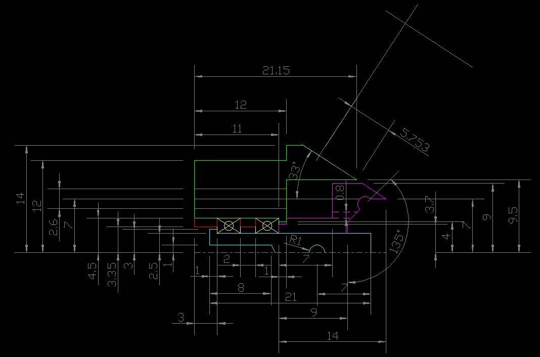
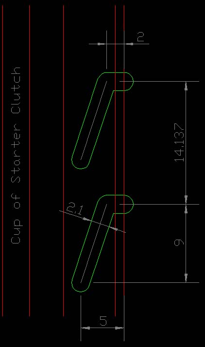
And here you can download two larger JPEGs of the drawings of the starter components. The first one is an axial section (upper half shown only). It should give an approximate idea of how the components are machined. The second image is a developed view of the helix. Since the diameter of the recess the helix is milled into is 9mm, the distance of 14.137mm between the two slots means that they are exactly opposing each other. The slots are to be milled with a 2.0mm end mill. Please click below to view the pictures:
If you need further information or DXFs of the drawings, please feel free to drop me a line:
07/28/2002
Yesterday I finished the mounting parts for the starter and drilled the corresponding bores in the
intake nozzle of my Behotec engine. As well the starter motor cover was made.
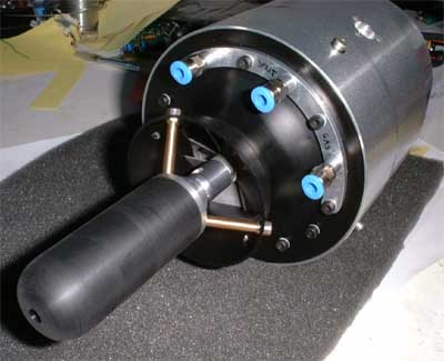 So heres the picture of the finished
starter assembly as mounted to the engine. The photo disturbs a little the correlation in size of the starter and the engine. Please disregard the mess in the background ;-).
So heres the picture of the finished
starter assembly as mounted to the engine. The photo disturbs a little the correlation in size of the starter and the engine. Please disregard the mess in the background ;-).
I tested the starter on a six-cell NiCd
and the current drain was tremendous for such a small motor. It draws about 25A initially which drops to about 16A when the speed settles. Consequently the motor gets really hot in no time.
Maybe Ill need a different motor with more turns, but maybe it will do just fine because it is only needed for a few seconds each start. Ill probably just have to try. But prior to this comes
finishing of my miniature HT ignition box (details to be published soon).
Addendum concerning the shaft and bearing arrangement: If I were to build another one, especially with a cheap motor (journal bearings), I would arrange the shaft extension differently. I machined my shaft from 6mm precision-ground silver steel and took off 1mm in diameter for the most of it. This was required to get the shim at the end that will prevent the shaft from slipping out of the bearings towards the turbine engine. Yet this required some really nasty surface finishing work because the 5mm part of the shaft extension needs to match the bearings as well as the clutch member precisely. Now I would immediately use a 5mm precision ground shaft and shrink a tube to it instead of the bearing spacer. This also eliminates any axial loading to the motor bearings. My current arrangement requires the rear motor bearing to carry the axial load during starting, which isn't a problem as long as a ball bearing motor is used. I hope I could make clear my concern...
07/29/2002 - The Zapper
Today I decided to build something really nasty :-), namely the ultimative model turbine engine
ignition. I already had a try at someting similar using a 555 timer as the oscillator but its output has way to little power to drive a MOSFET power switch fast enough. My main objective at this
design was to use only readily available parts, especially no custom-made inductors. It turned out that xenon flashlamp trigger coils are well capable of producing several kilovolts of AC for a
prolonged time if they are switched fast enough. What I turned up with is shown below.
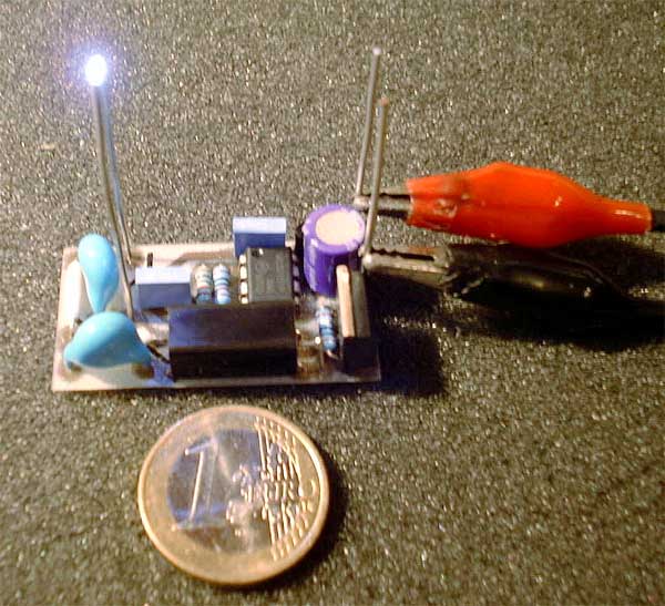
Here the complete ignition exciter is shown. The spark gap is about 3mm wide in this photo, but the circuit will be capable of throwing much longer sparks (up to 8...10mm). Yet it is required to cover it in resin or the high voltage will break down the PCB due to the small size. The Euro coin isnt the price of the unit but for a reference in size (at least to those who are familiar with the new European currency...). The total expense for the components is about 15 Euros (or Dollars US) less the PCB. The PCB is so simple that it could be made by vitually every hobby electronician. You can download TIFF files of the schematic and the PCB below.
Schematic Placeplan PCB Layout Bill of Materials
A word of warning: Though I dont think that an electric shock by this device would be fatal, it will definitely be very painful. So if anybody is going to build the ignitor to my specifications or similar, please be very careful when operating it. There might be high voltage present at the output terminals for some time even if the unit had been de-energised. And most important, I wont be liable for any damage or injury caused by a device built to this construction information.
And now some specifications:
Operating voltage: 7-12V, lower limit mainly depending on the gate threshold voltage of the MOSFET
Input current: ca.1A at 8V
Output voltage: up to 10kV, depending on the particular ignition coil used and the rating of the HT diodes and capacitors. The voltage needs to be limited by the spark plug. Dont used with open output terminals.
Switching frequency: ca. 50kHz
Operating mode: Intermittent, 30s on, 3 minutes off maximum
Physical size: 43*23*15mm³ approx., less terminals
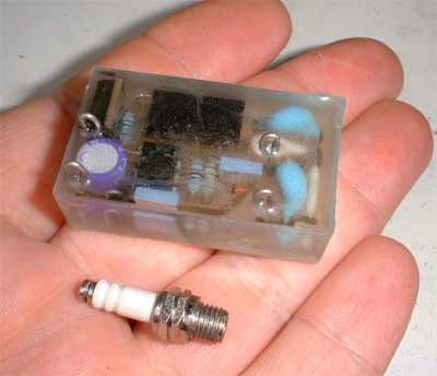 Heres the Zapper enclosed in epoxy
resin, shown together with the micro spark plug that Im going to use in my Behotec engine.It turned out that this unit will even light kerosine directly as long as its atomised to a fine mist.
Maybe now its time for a torch ignitor for a model jet engine to do away with the propane/butane preheat.
Heres the Zapper enclosed in epoxy
resin, shown together with the micro spark plug that Im going to use in my Behotec engine.It turned out that this unit will even light kerosine directly as long as its atomised to a fine mist.
Maybe now its time for a torch ignitor for a model jet engine to do away with the propane/butane preheat.