Jet Engine Electronic Control Unit
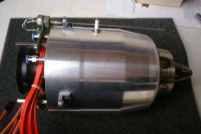
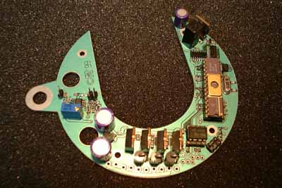
I started this project about September 1999, partly to learn more about jet engines, partly to obtain an ECU that fits mechanically on the circumference of the intake nozzle of my particular engine (Behotec JetStream 66 kit, http://www.behotec.de ), of course for fun, and definately not to save (or earn) money.
 If I had spent the time working on this
device on a paid job, I probably could have bought more than one JetCat Engine...
If I had spent the time working on this
device on a paid job, I probably could have bought more than one JetCat Engine...
And yet the ECU is far from being finished, although the hardware (almost) is. This project is therefore intended as
a non-profit one, maybe later on (when ...or if... we got the whole thing running) I will offer a kit of the ECU at the expense of the components plus a little fee for packaging and shipping. And now for the ECU:
Possible features:
- providing PWM output to the fuel pump, depending on thrust signal from receiver, current rpm and EGT
- monitoring EGT, battery voltage and ambient temperature
- monitoring rpm via an optical pickup (LED and Phototransistor) in a through-hole or reflective configuration
- providing power (PWM or switch) to an electrical engine starter motor
- providing a switch function for a propane valve (if an on-board propane tank is installed)
- controlling a status light (bright halogene bulb) to indicate engine problems, such as high EGT, low fuel, low battery voltage, emergency stop and so on. This seems to me much more convenient than
temporary idling the engine, like it is done on some other designs.
- providing ignition to the engine via a HT ignition coil and a spark plug. The ignition coil is of the
kind that is used for xenon flashlights and is intended for intermittent use only. Reliable operation of this design has to be veryfied. By adding a HT diode and capacitor it is also possible to provide a
high energy ignition. Both concepts work well with a gas burner.
- providing optical isolation of thrust and control signal from the receiver
- EEPROM offers the possibility to record all the parameters, especially total running time and cause of last shut-down, also the run-down time can be recorded (bearing condition).
- a terminal interface is included, providing RS232 control (CMOS level) of the engine by a notebook computer via a level shifter interface or by a (still to be designed) engine terminal box.
Future modifications:
- Some of you suggested to add a speed sensor (pitot tube and pressure sensor). I will probably add this feature to the design in a later version. The
circuitry to use a glow-plug for ignition will be added, too.
- For all of the rocketeers who are flying on propane or other gaseous fuels I might add a PPM output to control the throttle servo.
- On a suggestion a further switch output could be added to trigger an onboard CO2 fire extinguisher, controlled by the ambient temperature sensor. But I wonder if this wont be a little too much weight to the airframe.
- Maybe Ill add a vibration sensor, if that proofs useful for monitoring the bearing condition of the engine. This would possibly provide a much faster and earlier means of protecting the rotating
assembly from severe damage in case of a developing bearing failure, than simply measuring the spin-down time at shutoff.
-ECU Terminal, PC/Laptop interface adapter and PWM crowbar will be added soon (almost
finished in thoughts and as hand-drafts, but not yet entered to the CAD system.
And now for the most time-consuming part of the ECU (at least to me) - the microcode:
I started writing some basic routines for measuring and scaling of both of the R/C PPM inputs
(Control and Thrust) and also some basic inerrupt structure, all of this with Microchips MPASM
( http://www.microchip.com ). After a while I felt the whole thing to get a little bit difficult to survey, so
I searched the web for a free and easy-to-use compiler for the PIC micros. I found something called PICLite (http://www.myke.com) and used some of the assember routines and converted some others, but didnt get on a lot. Unfortunately the documentation of this compiler is a little bit sparse
(no critics, I think its quite honorable to offer a compiler like this on the web for free), and so is my spare time, so thats the current situation. I will offer everything concerning the ECU for download.
I think I will first try to implement the basic functions and not yet program a (PID) control loop and all the gimmicks mentioned above. The first working version should only provide a linear translation
from throttle r/c pulsewidth to fuel pump pwm output.It should also implement verification of the rpm and egt limits for the engine, as well as providing a means to control the acceleration/deceleration
ramps for the engine. Once these functions are working to our satisfaction, the program will be extended.
The schematics and layouts are designed with Target 2001 by Ingenieurbüro Friedrich, they offer an evaluation version of their program on their web page (http://www.ibfriedrich.com) for download. This version should be sufficient for viewing and printing of both schematics and layout, generating parts lists or even exporting netlists to transfer the whole project to another CAD system.
Changes 07/20/2000:
- The code will definately be written in C and Assembler because this is simply much more convenient and much better documented.
- The PIC 16C73 will be replaced by the PIC 18C252, wich has the same pinout (at least the OTP version) and is so much superior.
- I will probably test the ECU on my turbocharger engine until Im sure it wont rip the Jetstream 66 apart.
Added 01/12/2001
Progress, progress ;-). You might not have believed that there will be added something to this part of my site ever, but , well, IT WILL! Though not really a breakthrough, but something that will make it much easier for me to continue programming work! I just finished the RS232 transceiver (less the cable) to connect the ECU to a PC. This will make checking individual software modules much easier and straight-ahead.
![]() This transceiver was really not much
effort, but it still had to be built. So I hope, if it works correctly, that I will add some news here soon!
This transceiver was really not much
effort, but it still had to be built. So I hope, if it works correctly, that I will add some news here soon!
09/08/2002
Its been a long time since my last extension to this part of my web site and unfortunately theres little news about the project. Its simply that I have too little time to do all the extensive software development by myself. But I had some inquiries for construction information for this project since I removed the files from the server to free up the space. So here they are again:
The files:
Compressed archive of schematics, please use Target by IBF to view and print the files: Download (45kB)
PicBasic Pro / assembler microcode (still far from completion): Download (14kB)
Some details that have changed: Once again the processor had been changed, now its a PIC16F876 because of its electrical erasability. This will speed up software development a lot. I also purchased a copy of PicBasic Pro by Micro Engineering Labs to simplify programming of the math routines and the sequencing engine. To keep the code fast the interrupt service routines will be kept in assembler. For a new hardware revision I would opt for a separate ignition mechanism so everyone can use the ignition method he prefers (HT spark, glow plug or manual), please see my KJ Starter page for details of a HT ignition module. The ECU would only activate the power to the ignition device.
And once again, please be aware that this is a development project. It is far from being finished, not even usable at all at this time. I would appreciate any and all sopport at developing the microcode for this unit. It wont need to be written in Basic / assembler but since these are the only programming languages Im half-way familiar with, I chose them. Dont start building anything to the information above if you expect a fully functional model turbine ECU as a result. Its still way to go to this point.