Jürgens Shaft Turbine Engine
This page describes the genesis of a shaft turbine engine, built by Jürgen Wagner, a friend of mine. He does all the building and most of the construction work, yet Im involved in this project as a consultant. He gave me the permission to place the pictures of his engine on my page as he doesnt intend to set up a web site of his own currently.
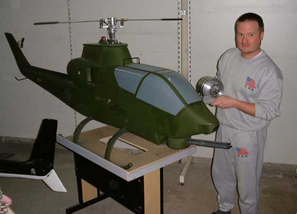
Here is Jürgen standing close to one of his helicopters (Cobra, less rotor blades and stub wings), his turbine in his hands. He designed and built this giant model helicopter (about 3m rotor diameter) all by himself and finally came to a point where he found that theres little to improve on this design. So he searched for a new challenge. It should have to deal with helicopters of course, and so the logically next step would be powering one of his monsters with a shaft turbine engine. That was the time that he got into contact with me (a little less than a year ago) by means of this web site of mine. Of course I was completely fascinated by his idea and as it turned out that we live at places just about one hour of driving distance we met a few times and discussed the details. And after a lot of work Jürgen got his engine to a point that it already looks like something. So here are the pictures.
 We discussed which engine concept
would work best for a helicopter turbine engine and I voted for a single shaft layout because its much easier to operate it at a constant speed. And this is esseantial for a helicopter. The rotor head RPM must not vary,
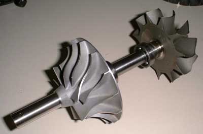
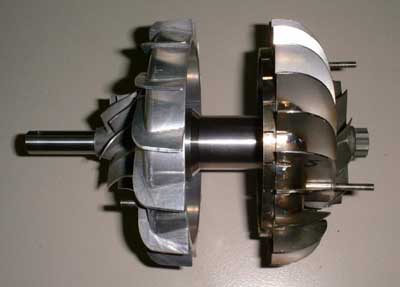
regardless of the pitch setting. To keep things simple and affordable we agreed to use a complete turbocharger rotor. This one is a spare for a 3K-Warner K29 turbocharger. The compressor has a
diameter of 88mm, the turbine one of 81mm. The design shaft output power is 8kW. In principle a modified KJ66 engine should be capable of this power as well but this
would require rotor speeds of about 120k rpm. The compressor of this engine has similar pressure and flow characteristics like the 2038 of the KJ66 but at speeds of only 80k rpm.
Nevertheless the real challenge might become the gearbox.
We discussed which engine concept
would work best for a helicopter turbine engine and I voted for a single shaft layout because its much easier to operate it at a constant speed. And this is esseantial for a helicopter. The rotor head RPM must not vary,
regardless of the pitch setting. To keep things simple and affordable we agreed to use a complete turbocharger rotor. This one is a spare for a 3K-Warner K29 turbocharger. The compressor has a
diameter of 88mm, the turbine one of 81mm. The design shaft output power is 8kW. In principle a modified KJ66 engine should be capable of this power as well but this
would require rotor speeds of about 120k rpm. The compressor of this engine has similar pressure and flow characteristics like the 2038 of the KJ66 but at speeds of only 80k rpm.
Nevertheless the real challenge might become the gearbox.
I was lucky to get hold of the flow maps of both turbine and compressor wheels so I started calculation of diffuser and NGV. We thought about 3D-milling these components from full material but finally Jürgen decided to build them manually.
 So heres the diffuser. Jürgen made
this according to the Kamps book out of a machined plate and vanes made of sheet material, glued in slots. The overall diameter of this engine is about 150mm
So heres the diffuser. Jürgen made
this according to the Kamps book out of a machined plate and vanes made of sheet material, glued in slots. The overall diameter of this engine is about 150mm
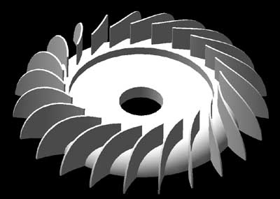 Thats what the NGV should look like,
according to my calculations. The relatively high count of vanes is required to keep the flow area of the nozzle small enough to obtain the required gas velocity at the inlet to the turbine wheel.
Thats what the NGV should look like,
according to my calculations. The relatively high count of vanes is required to keep the flow area of the nozzle small enough to obtain the required gas velocity at the inlet to the turbine wheel.
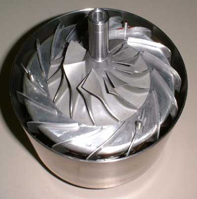
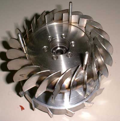 And thats what the actual NGV looks
like. It is a most beautyful piece of engineering and required a lot of work to complete so far. Yet we are discussing if we could possibly replace the three mounting bolts for the turbine cover to a different
location with less gas velocities. The original design with the machined vanes would have made mounting of the turbine cover much easier because each of the vanes could have had a threaded bore to screw
the cover to. Well try out the NGV and should the three bolts affect the efficiency too much well look out for another option.
And thats what the actual NGV looks
like. It is a most beautyful piece of engineering and required a lot of work to complete so far. Yet we are discussing if we could possibly replace the three mounting bolts for the turbine cover to a different
location with less gas velocities. The original design with the machined vanes would have made mounting of the turbine cover much easier because each of the vanes could have had a threaded bore to screw
the cover to. Well try out the NGV and should the three bolts affect the efficiency too much well look out for another option.
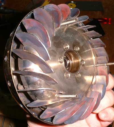
 Here you can see how snugly the
turbine fits into the NGV.
Here you can see how snugly the
turbine fits into the NGV.
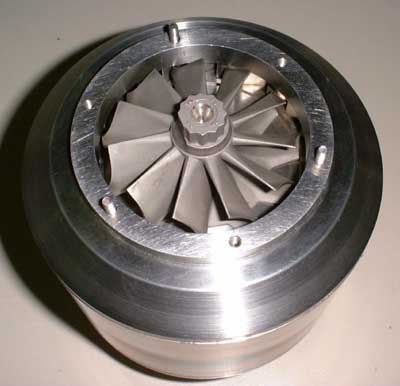
 And thats the complete core of the
engine less the combustor. Theres amazingly little space left for the flame tube but it may project almost 10mm into the cavity formed by the back of the compressor diffuser. Due to its large diameter it will yet have a larger
volume than the KJ66 combustor. I made a quick-and-dirty sketch of the combustor for Jürgen and he will try to press some stainless steel parts to shape so well be able to find out if we can proceed this way. The combustor
will be an eight-stick design, each stick slightly bent to an S-shape. If everything during machining will turn out well, well get a very strong recirculation.
And thats the complete core of the
engine less the combustor. Theres amazingly little space left for the flame tube but it may project almost 10mm into the cavity formed by the back of the compressor diffuser. Due to its large diameter it will yet have a larger
volume than the KJ66 combustor. I made a quick-and-dirty sketch of the combustor for Jürgen and he will try to press some stainless steel parts to shape so well be able to find out if we can proceed this way. The combustor
will be an eight-stick design, each stick slightly bent to an S-shape. If everything during machining will turn out well, well get a very strong recirculation.
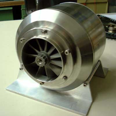
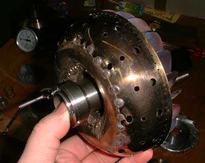
 Thats a view onto the rear of the
engine with the exhaust section cover for the turbine wheel removed
Thats a view onto the rear of the
engine with the exhaust section cover for the turbine wheel removed
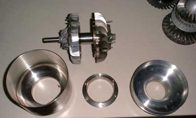 These are the components finished
so far. In the centre the core, from left to right turbine housing with turbine cover, exhaust section cover and compressor intake. In the top right corner theres part of a KHD T-312 APU rotor that I brought with me for
display. Unfortunately not a part of this engine, but I guess 110kW would be slightly too much for this helicopter application...
These are the components finished
so far. In the centre the core, from left to right turbine housing with turbine cover, exhaust section cover and compressor intake. In the top right corner theres part of a KHD T-312 APU rotor that I brought with me for
display. Unfortunately not a part of this engine, but I guess 110kW would be slightly too much for this helicopter application...
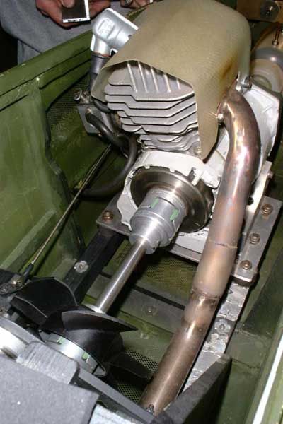
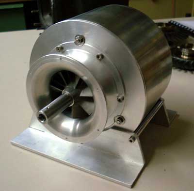 The engine as viewed from the front
and located on the mounting base. The gear box will mount to the front of the intake. We are not quite sure which way to go with the reduction gear but a planetary one would probably be best. Well also have to
figure out how to attach the pinion gear to the turbine shaft. Well probably need some kind of quill shaft to couple the stub shaft in front of the compressor to the pinion gear shaft and to compensate for small radial
and angular displacements. But this is future music, well have to get this beast running first.
The engine as viewed from the front
and located on the mounting base. The gear box will mount to the front of the intake. We are not quite sure which way to go with the reduction gear but a planetary one would probably be best. Well also have to
figure out how to attach the pinion gear to the turbine shaft. Well probably need some kind of quill shaft to couple the stub shaft in front of the compressor to the pinion gear shaft and to compensate for small radial
and angular displacements. But this is future music, well have to get this beast running first.
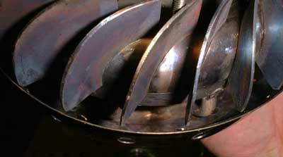
 Thats the business end of the
turbine. Im really curious of the first time well fire this baby up.
Thats the business end of the
turbine. Im really curious of the first time well fire this baby up.
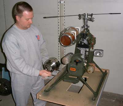 Heres Jürgen next to his
experimental helicopter (less baldes and tail-boom). This will be the airframe that the turbine engine goes into. The cylindrical enclosure to the left of the helicopter is a vibration- dampened cabinet for a camcorder.
The problem is that the two-stroke engine that currently powers the helicopter produces still too much vibration. This results in disturbed videos as it affects the VCR mechanism in the camcorder. A gas
turbine engine will eliminate this problem completely.
Heres Jürgen next to his
experimental helicopter (less baldes and tail-boom). This will be the airframe that the turbine engine goes into. The cylindrical enclosure to the left of the helicopter is a vibration- dampened cabinet for a camcorder.
The problem is that the two-stroke engine that currently powers the helicopter produces still too much vibration. This results in disturbed videos as it affects the VCR mechanism in the camcorder. A gas
turbine engine will eliminate this problem completely.
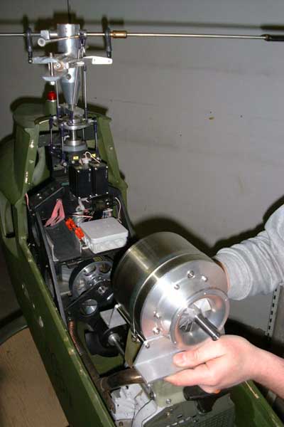 Heres a shot of the helicopter
mechanics. Theres lots of space for the turbine in the fuselage of this helicopter. If the engine turns out to be capable of the calculated power, the helicopter would easily be able to lift 20kg of payload. Yet the fuel
consumption would need to be considered in this calculation.
Heres a shot of the helicopter
mechanics. Theres lots of space for the turbine in the fuselage of this helicopter. If the engine turns out to be capable of the calculated power, the helicopter would easily be able to lift 20kg of payload. Yet the fuel
consumption would need to be considered in this calculation.
 Thats the current powerplant of the
helicopter. Its a powerful two-stroke gas engine of a Stihl chainsaw. This motor produces about 7hp at a weight of slightly more than 4kg. The turbine so far weighs a little more than 3kg, but this could be reduced by about
1kg if some of the components (especially the turbine rear cover) are built more light-weight. But for the first experiments we dont bother about this. Once the turbine runs properly we will find ways to reduce its weight.
Thats the current powerplant of the
helicopter. Its a powerful two-stroke gas engine of a Stihl chainsaw. This motor produces about 7hp at a weight of slightly more than 4kg. The turbine so far weighs a little more than 3kg, but this could be reduced by about
1kg if some of the components (especially the turbine rear cover) are built more light-weight. But for the first experiments we dont bother about this. Once the turbine runs properly we will find ways to reduce its weight.
Its been a long time since I published some lines to this part of my page, but yesterday was quite remarkable as I visited Beate and Jürgen once again. The day before, Jürgen phoned me up and told me that he got his turbine engine running for the first time. Though very excited, he seemed not yet satisfied with the results so far and asked for some advise. And since I had my GTP30 in the trunk of my car I thought it was a good opportunity to show this to Jürgen at the same time. I can tell you we had some fun :o). But first some photos:
 Heres the combustor shown together
with the NGV. The major part of the front section was a marmelade funnel in its prior life. Jürgen machined the inner part and the rear wall of this combustor from solid stock, drilled the air passages and welded it all
together. Even though the combustor is very short in length, it contains the flame very well, at least as long its fired with propane. Theres still some space left so it could have been made
longer, but the shape of the kitchen accesory dictated the combustor size. The unit discolours perfectly even and never flamed out so far. Im a little in doubt if it will still work so fine when we switch to liquid fuel...
Heres the combustor shown together
with the NGV. The major part of the front section was a marmelade funnel in its prior life. Jürgen machined the inner part and the rear wall of this combustor from solid stock, drilled the air passages and welded it all
together. Even though the combustor is very short in length, it contains the flame very well, at least as long its fired with propane. Theres still some space left so it could have been made
longer, but the shape of the kitchen accesory dictated the combustor size. The unit discolours perfectly even and never flamed out so far. Im a little in doubt if it will still work so fine when we switch to liquid fuel...
 Thats the NGV side of the
combustor/NGV unit. The NGV is simply slipped onto a recess in the rear wall of the combustor. We finally found a way to do away with the three turbine cover bolts that restrict the gas flow in some NGV passages. this
is one of the modifications Jürgen will do soon.
Thats the NGV side of the
combustor/NGV unit. The NGV is simply slipped onto a recess in the rear wall of the combustor. We finally found a way to do away with the three turbine cover bolts that restrict the gas flow in some NGV passages. this
is one of the modifications Jürgen will do soon.
 Heres a shot into the annular orifice
between the front and the back member of the combustor. One of the vaporiser sticks can be seen in the right half of the picture.
Heres a shot into the annular orifice
between the front and the back member of the combustor. One of the vaporiser sticks can be seen in the right half of the picture.
 Thats the rear of the combustor, this
time less the NGV. The back plate is wired to the center tube, as is the fuel distribution ring. The combustor is equipped with eight vaporiser tubes that are bent to point to the center of the assembly. These sticks are made
of the tube of a heating element off of an oven or an electric BBQ set. Thats about the least expensive source for Inconel tube in small quantities.
Thats the rear of the combustor, this
time less the NGV. The back plate is wired to the center tube, as is the fuel distribution ring. The combustor is equipped with eight vaporiser tubes that are bent to point to the center of the assembly. These sticks are made
of the tube of a heating element off of an oven or an electric BBQ set. Thats about the least expensive source for Inconel tube in small quantities.
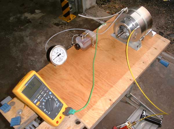
And thats Jürgens engine test bed (the thermometer belongs to me...). He has attached an ultra-low pressure gauge (range from -10 to +60mbar) to have a good reading of the compressor delivery pressure during first engine evaluation. The oil tank has got a pressure feed system but it didnt function too well with the low pressures we encountered so far. So Jürgen decided just to give the engine a squirt of oil now and then. If the bearings should suffer from this lubrication method it wouldnt be a financial disaster because they are just standard steel types, no hybrids yet. The combustor is supplied with gaseous propane from a steel bottle, through a pressure regulator that outputs 3.5bar.
The consequent test runs revealed that this pressure might be a little low for a stable idle, but there are more factors that might cause inefficiencies. Jürgen made all the components to very exact tolerances, and in some places he just did too good a job ;-). For instance the space between the back face of the compressor wheel and the front face of the compressor diffuser pocket is just about 0.1mm and every drop of oil that gets into there will cause a lot of drag to the rotor. Jürgen looked a little unbelievingly as I told him to allow a clearance of 0.5 to 1mm behind the compressor wheel. There are a few more such details that need to be rectified and, most important, he will need to use the hybrid bearings as the steel ones that had already been used as gauges during manufacturing of the shaft tube, have definitely seen better times.
So have a look at this clip if you please, you would need to have the DivX codec:
Almost idling.avi (1,5MB)
If you ask me, I would say were pretty close :-).
 And just in case we wont be
successful with our combustor design, heres the way to go ;-).
And just in case we wont be
successful with our combustor design, heres the way to go ;-).
(Book on witchcraft)
About one week after my visit to Beate and Jürgen, he happily phoned me up and told that he has done all the suggested improvements, though still the bolts restrict the NGV. But the engine idles at just 15mbar case pressure with an EGT of less than 600°C. It easily accelerates from there to a speed that is limited by the flow rate hes getting from his propane bottle and the pressure limiter. Anyway, it is a great success that his engine is running flawlessly so far. Well see how things develop when the combustor tastes liquid fuel for the first time...
To be continued.
Please send questions or comments to Contact ,
or directly to Jürgen Wagner at WagnerHelicopter(at)gmx.net .