Garrett AiResearch GTCP85
The GTCP85 air compressor/shaft power engine in its many variants is an ubiquitious engine, used as airborne APU in many famous aircraft such as the Boeing 737, KC135, Breguet Atlantic, Transall to name just a few. Moreover, it has been utilized in several ground power/support units, some also providing heating/cooling functions for field hospitals or the like. Combined power (air/shaft) of most units is in the region of 200hp at a shaft speed slightly above 40,000 RPM. Garrett AiResearch started design of this engine in the early 1950s but later on, several improvements have been added. The basic design of the GTCP85 is similar on all the versions, featuring a two-stage radial compressor, a single stage radial turbine and a single, reverse flow, can-type, tangentially mounted combustion chamber with a single duplex fuel nozzle to atomize the fuel. One peculiar detail of this engine is the double-entry first stage radial compressor, requiring an assembly of individual air ducts from the first stage compressor discharge to the second stage compressor inducer plenum. This is necessary to permit air flowing to the rear intake of the first stage compressor. Despite its high production quantitiy, little in-depth information on that engine can be found on the web. If someone has got a manual for the GTCP85, especially in electronically distributable format, I would be happy if he could provide me a copy...
I got my hands dirty on a GTCP85-160 since I sourced one of these units for a company that intends to use its air output to power some experimental machinery. I was charged with basic wiring and instrumentation of the “monster” to get it running.
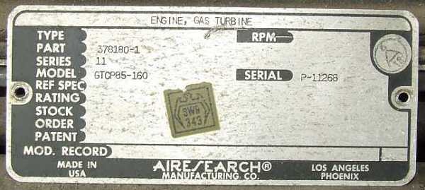 |
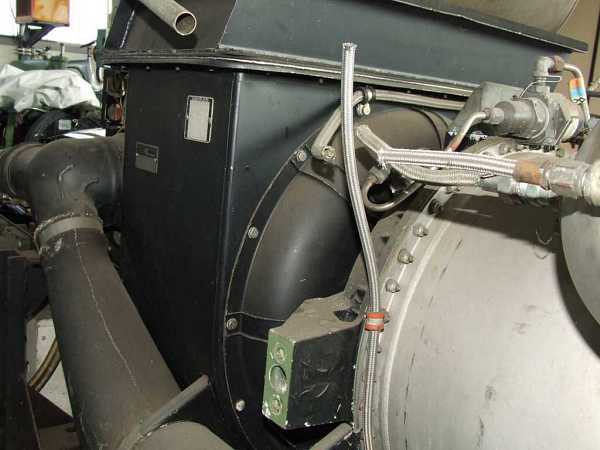
The “dash 160” model of the GTCP85 was used in a ground support unit for F-104 “Starfighter” and F-4 “Phantom” aircraft. This particular GPU must have been phased out of the inventary of the German “Luftwaffe” as these aircraft have been removed from service. To render it inoperational, the ignitor lead as well as the fuel hose form the FCU to the fuel nozzle have been clipped - not too difficult to fix ;-).
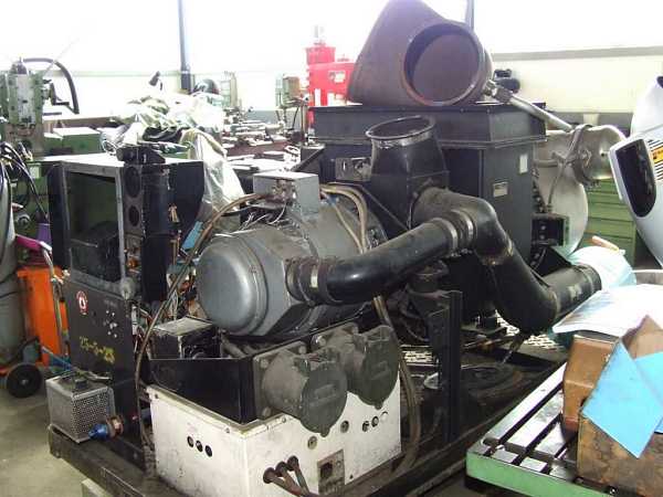
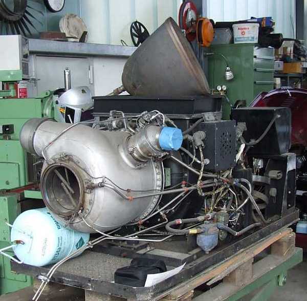
That’s what the engine looked like when I negotiated the purchase:
 |
 |
 |
 |
 |
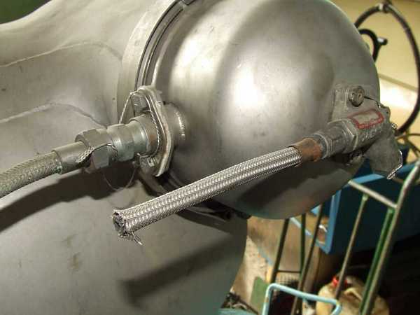 |
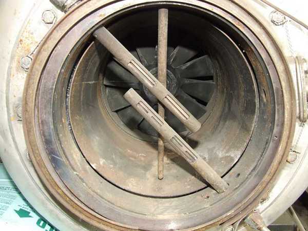
The last two photos show the clipped lead/hose. The oil tank has been previously removed by someone as well as the complete control panel. The engine was quite dirty but turned over freely and I got the impression that it is mechanically in acceptable condition. So I decided to go for it...
I’ve got a manual of a ground support unit with a different dash number of the GTCP85 that covered the engine at least superficially. I hoped the available information would help me to get the thing going since the hydropneumatic and electrical systems, though not really high-tech, were at least quite complex.
 |
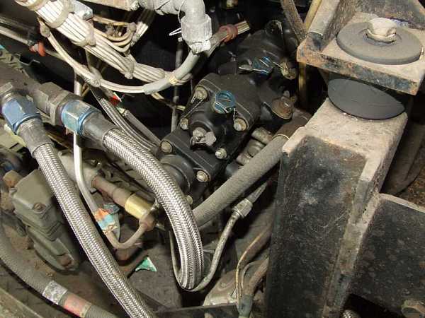 |
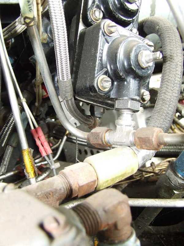
These two photos show parts of the FCU and give an impression of the plumbing and wiring to be sorted out...
 |
This is a schematic of the basic engine setup, also showing the fuel control unit (FCU - click the pichture for a larger version). The FCU design is typical for the early Garrett AiResearch auxiliary engines, providing RPM stabilisation by a flyweight governor, acceleartion control by compressor delivery pressure (CDP) operated differential pressure valve that’s also used to limit EGT in case excessive load is applied. The bleed air valve is also EGT-controlled by a pneumatic thermostate that operates at a slightly lower temperature than the FCU control thermostate. This configuration makes it possible to open the bleed air valve without a load attached. The butterfly valve will only open so far as not to overload the engine.
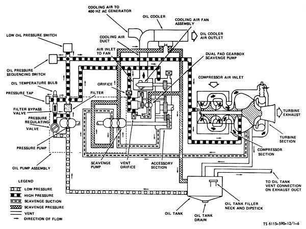 |
This sketch shows the basic layout of the lubrication system, being of the dry sump type and requiring an external oil tank. The “-160” engine is of the older “four bearing” design and requires still some more oil injection nozzles. Yet, since I expected that the lube system would work without much hassle, I was not too concerened about the discrepancy between the information avaialble and the actual engine setup.
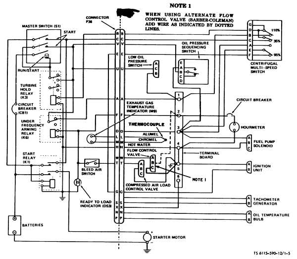 |
The electrical system gave me more headache since the wiring was very confusing with the sensors and actuators distributed all over the engine, making it virtually impossible to figure out the schematic completely. Moreover, there was one more relay present on the engine than shown in the above schematic and the other relays also had more terminals... Whatsoever, eventually I figured out the basic function of the individual wires and got the electrical system working.
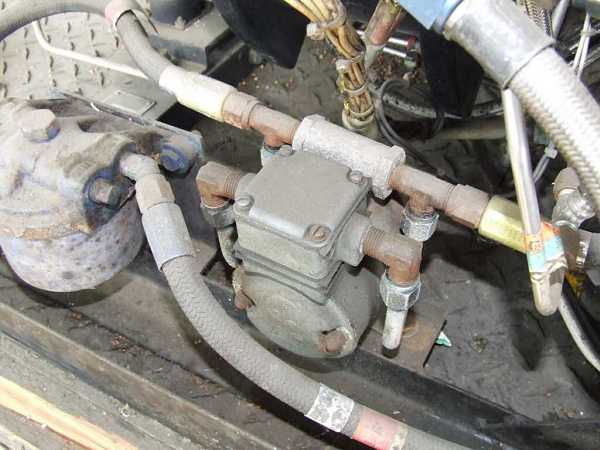
Startup sequencing is accomplished by a “centrifugal multi-switch” to cut out the starter and ignitor and to enable the airbleed solenoid at the appropriate engine RPM. Moreover, it will shut down the engine if RPM exceeds 110%. One somewhat peculiar detail is the fuel boost pump wired in parallel with the starter so it will only supply additional fuel pressure during engine startup. It is bypassed by a check-valve so after it’s shut down, the fuel will flow directly without restriction by the pump:
 |
Since I didn’t tear down the engine, I wasn’t able to take photos of its internals. Hence I searched my archive for photos that I occasionally downloaded from the web. If the original owners of the photos feel offended or would like to have their names mentioned, please just drop me a line and I will either remove the photo or add detailed copyright information. Sorry for that...
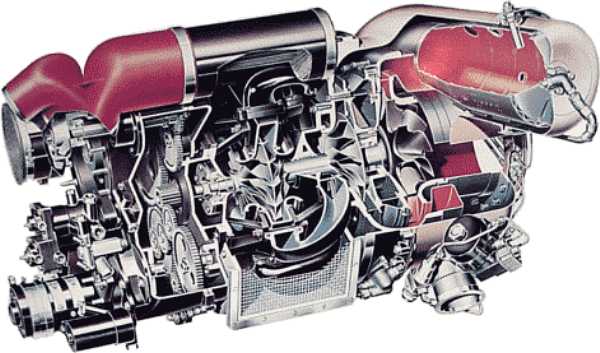 |
That’s a sectioned drawing of the more recent “two bearing” version of the GTCP85, yet the basic configuration is similar to the “four bearing” predecessor.
 |
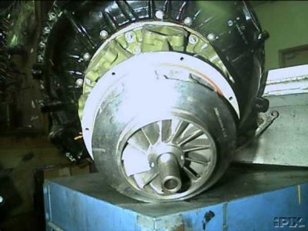
Here a cross-section of the “four-bearing” version shown. The turbine rotor and the compressor rotor are separate assemblies, each one suspended in two bearings (a ball and a roller bearing) and connected with a splined coupling. Initially, this was the way the engineers decided they can better control the shaft resonances. Another peculiarity that the early engines featured is the shrouded first stage compressor impeller:
 |
 |
The turbine wheel consists of two separate parts - the impeller and the exducer. The two parts are riveted together by a substantial annular rivet (like a tube segment) that is staked into specially shaped annular slots in the impeller and exducer. Probably during assembly, the rivet metal heats up high enough to shrink the two sections together during cooldown so the elastic deformation of the rivet was compensated. Quite a clever design feature! Yet, nowadays the wheel would be cast integrally (and I guess the later versions for the GTCP85 were...).
 |
That’s what the panel looks like so far... Not yet finished, some brackets for the RPM and EGT gauge will need to be fabricated and a bleed air pressure gauge will be added in the empty hole. Yet, all the functions to get the engine running have been figured out. Since only the bleed air will be required in the installation that it’s intended for, the alternator has been removed and all the accompanying circuitry pulled. The two switches for the fuel valve and the ignition exciter are not really necessary, yet they permit testing of these accessories without actually performing a start. To start the engine, the main power switch is closed and then the start switch is pushed momentarily - that’s it! When the engine has reached governed speed, the airbleed switch can be actuated to open the butterfly valve.
And that’s what’s left to do... cleaning!
 |
All those who would like to see the result of the effort, please click here! A GTCP85-160 operated by “yours truly”... :-)