Exposition of “Motorenfabrik Oberursel”
(Engine Factory Oberursel)
Today, on 07/04/2001 on a beautyfull day me and my dad decided to visit a temporary exhibition of the “Motorenfabrik Oberursel” (that was the name about 1900, later better known as Klöckner-Humboldt-Deutz, KHD and afterwards taken over by BMW-Rolls Royce). Oberursel is only at about 20 minutes driving distance from my place, so I might consider taking a second look at the displayed engines.
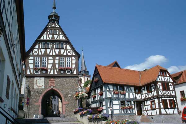
That’s a view from the entrance of the building the exhibition is located in at the historic center of Oberursel. The museum is to the left, to the right hand there’s the marketplace.
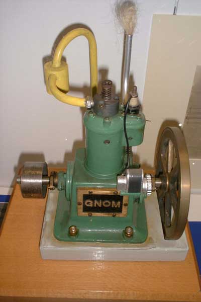 The “Motorenfabrik Oberursel” had
its origin in a single technician who built in the closing 19th century a small kerosine motor called “Gnom” that was able to produce about 4hp at a then surprisingly small size and weight. It was widely used to power
all kinds of stationary appliances. “Gnom” (gnome) was mockingly said to be the abbreviation of “Geht nicht ohne Mechaniker” (won’t work without a mechanic).
Later a series of radial aircraft engines with revolving cylinders and crankcase was develeoped for the early attempts of human flight.
After the second world war most of the factory was disassembled and confiscated by the allies.
Later the factory was re-established to design and build large turbochargers for reciprocating engines.
This led to the development of small gas turbine engines for target drones and auxiliary applications. As well other companies’ engines were manufactured under license
Now the pictures of the exposed turbines follow. Some of the displayed items were placed behind glass so I must apologise for the reflections or poor quality in some of the pictures.
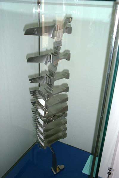 A slice of a compressor drum of one
of the larger engines built. A nice view of the different compressor discs.
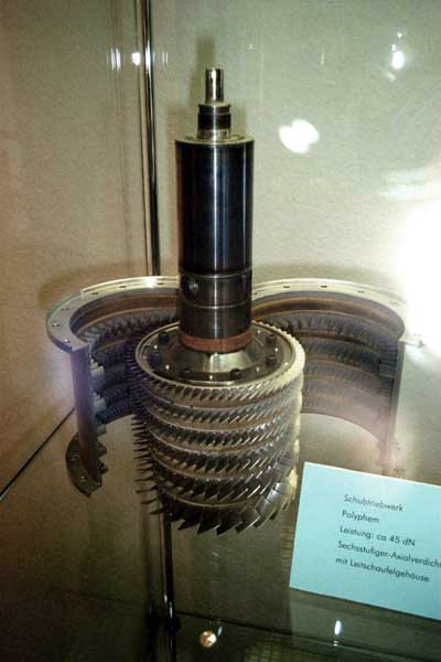 This and the following picture show
some of the components of a very small propulsion engine (“Polyphem”) that never went into production. The diameter of this engine is only about 120mm, its length about 400mm. The engine is specified to produce 450N of thrust.
To conclude from the profile of the compressor rotor blades this small axial compressor is designed to operate in the supersonic range. Unfortunately the compression ratio of this miniature six-stage axial
compressor isn’t specified. Who is going to build something like this to power a model aircraft? ;-)
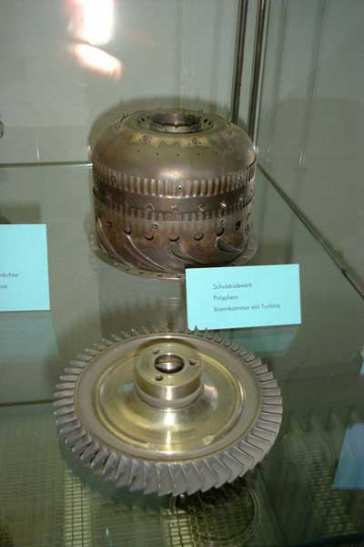 The combustion chamber with
integral hollow NGV and the turbine blisk of the “Polyphem”
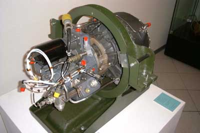 A small engine designed to power
light-weight training aircraft in twin-engine arrangement. This engine is of a very simple and reliable design (single-stage radial compressor, single-stage axial turbine) and will produce a thrust of 1000N.
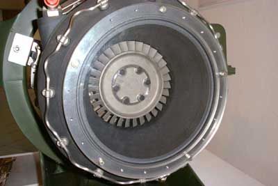 That’s a view into the “hot end” of the
above engine.
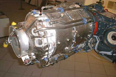 The following series of pictures show the KHD T 312 APU system that had been designed for the “Tornado” combat aircraft. This system generates shaft power, hydraulic
pressure as well as compressed air at a total output of approx. 100kW. More info on this engine here! Please click on the photos of this engine for high resolution versions.
Here the APU turbine engine is visible as well as part of the gear train.
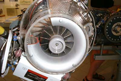 The intake nozzle of the engine as seen directly from the front. The overall diameter of this turbine engine is approx. 300mm.
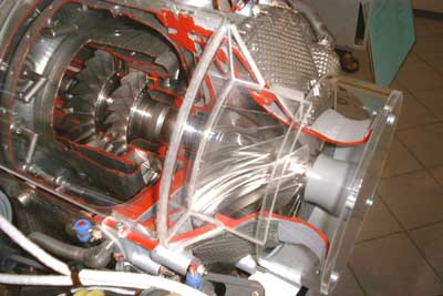 The compressor and both turbine sections. Both of the turbine blisks are mounted on a single shaft that drives the reduction gear as well.
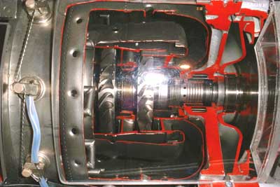 The reverse flow combustion liner is clearly visible, a design that provides troublefree operation of many compact turbine engines in the lower power segment.
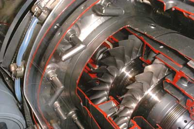 The two turbine stages (wheel diameters of about 120mm) and the vaporiser sticks located at the end of the combustor liner.
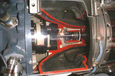 That’s the first stage of the epicyclic reduction gear.
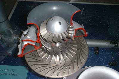 Here the earlier version of the T 312 compressor is shown. It features a simple radial wheel with straight-ended vanes and an axial booster stage in front to increase the
compression ratio. The profile of the axial wheel’s vanes reveal that this axial stage operates at supersonic speeds.
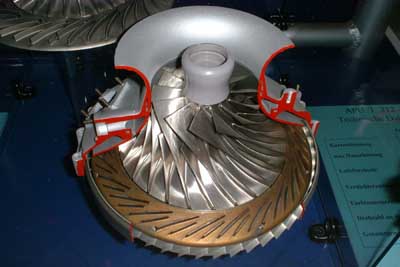 That’s the recent version of the T 312 compressor with a much more sophisticated high-compression ratio radial wheel.
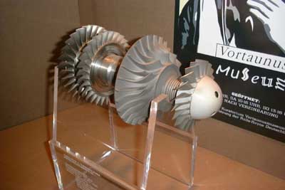 Here’s the complete rotor of the T 312 shown. This is the earlier version with the axial booster stage. This item was found at a different location in the museum
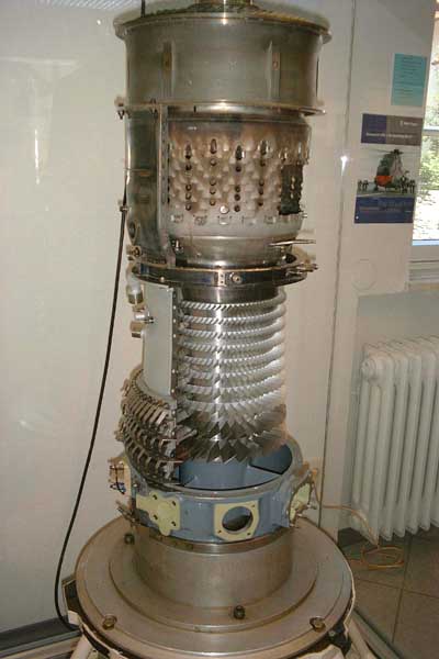 A Rolls-Royce Gnome engine, built
under license. This engine, capable of approx. 1500hp, is often used in twin arrangements to power larger helicopters.
The pitch of the lower few rows of stationary compressor vanes is adjustable to match the flow characteristics of the engine at partial load.
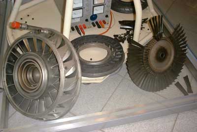 Two NGVs of the Gnome and a
power turbine wheel with some of its blades removed.
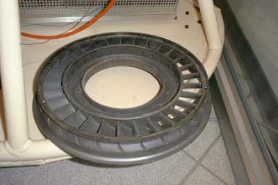 A first-stage NGV of the Gnome. The
vanes are hollow to allow for cooling from the inside.
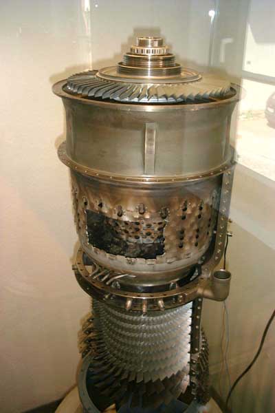 The combustion and turbine section
of the Gnome with a part of the combustor liner outer wall cut out to be able to take a look at the inside
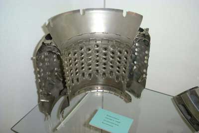 A slice of a Gnome combustor liner.
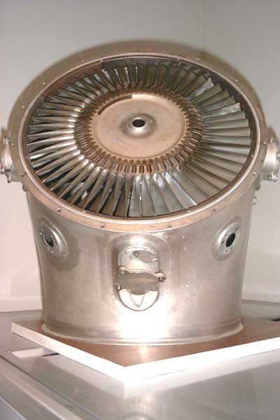 The power turbine and exhaust volute
section of the Gnome engine. Each of these 54 blades contributes 28hp to the output power at just about 80mm length. The power density of these engines is truely staggering.
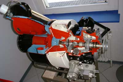 A 100hp industrial turbine engine,
used to power pumps and mobile alternator systems. This engine has very much in common with the Garrett AiResearch “GTP” APU series. Some features are the overhung rotor shaft, i.e. no bearings
in the hot sections, single radial compressor and turbine wheel and single tangentially mounted combustion chamber. Though heavier and more bulky than coaxial designs, these engines are very
reliable, tough little power plants. In the top right of the picture the hand crank for starting the engine is visible.
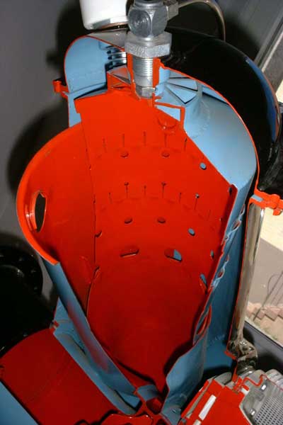 That’s a shot into the sectioned
combustion chamber. Except for the swirl vanes around the fuel nozzle on the top this combustor consists completely of sheet metal. It should be well possible for an amateur to build something like this to convert a
turbocharger into a turbine engine.
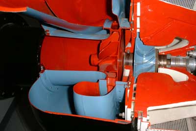 Though this engine incorporates a
volute (snailshell housing) to duct the combustion gases to the turbine wheel, still a ring of stationary guide vanes is used. These wheels are about 150mm in diameter.
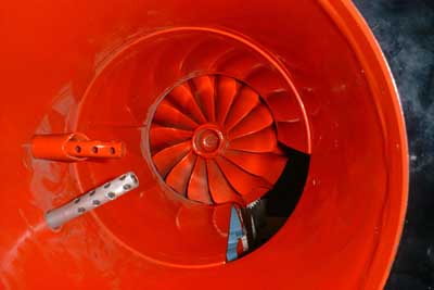 Mostly red... This is a shot up the
exhaust duct with the exducer vanes of the turbine wheel and two thermocouples. I guess if the engine takes this colour during operation it will distribute its guts all over the place ;-)
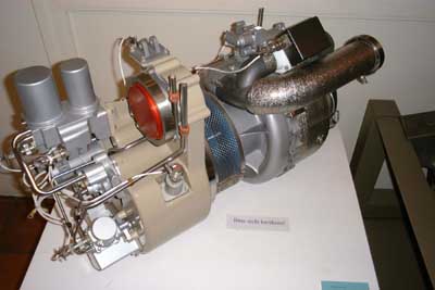 This engine was placed at a different
location of the museum. It looks very much like a Microturbo Saphir from the general design point of view, but besides of 200kW of compressed air it will as well supply about 17kW of shaft power (if I remember
correctly). It is probably intended as an APU mainly for starting the propulsion engines of an aircraft.
Ok, that’s it! I hope you enjoyed the pictures of those fascinating engines as much as I enjoyed visiting the museum. If you want to get some of these pictures at a higher resolution, you’re welcome to email me. I’ve got all of these photos at 1800*1200 pixels, but those are large...